Tel: 0086-2587156578 Web: www.omc-stepperonline.com
Email:sales@stepperonline.com
3
Full Digital Stepper Drive DM860T
3. Pin Assignment and Description
The DM860T has two connectors, connector P1 for control signals connections, and connector P2 for power and motor
connections. The following tables are brief descriptions of the two connectors. More detailed descriptions of the pins
and related issues are presented in section 4, 5, 9.
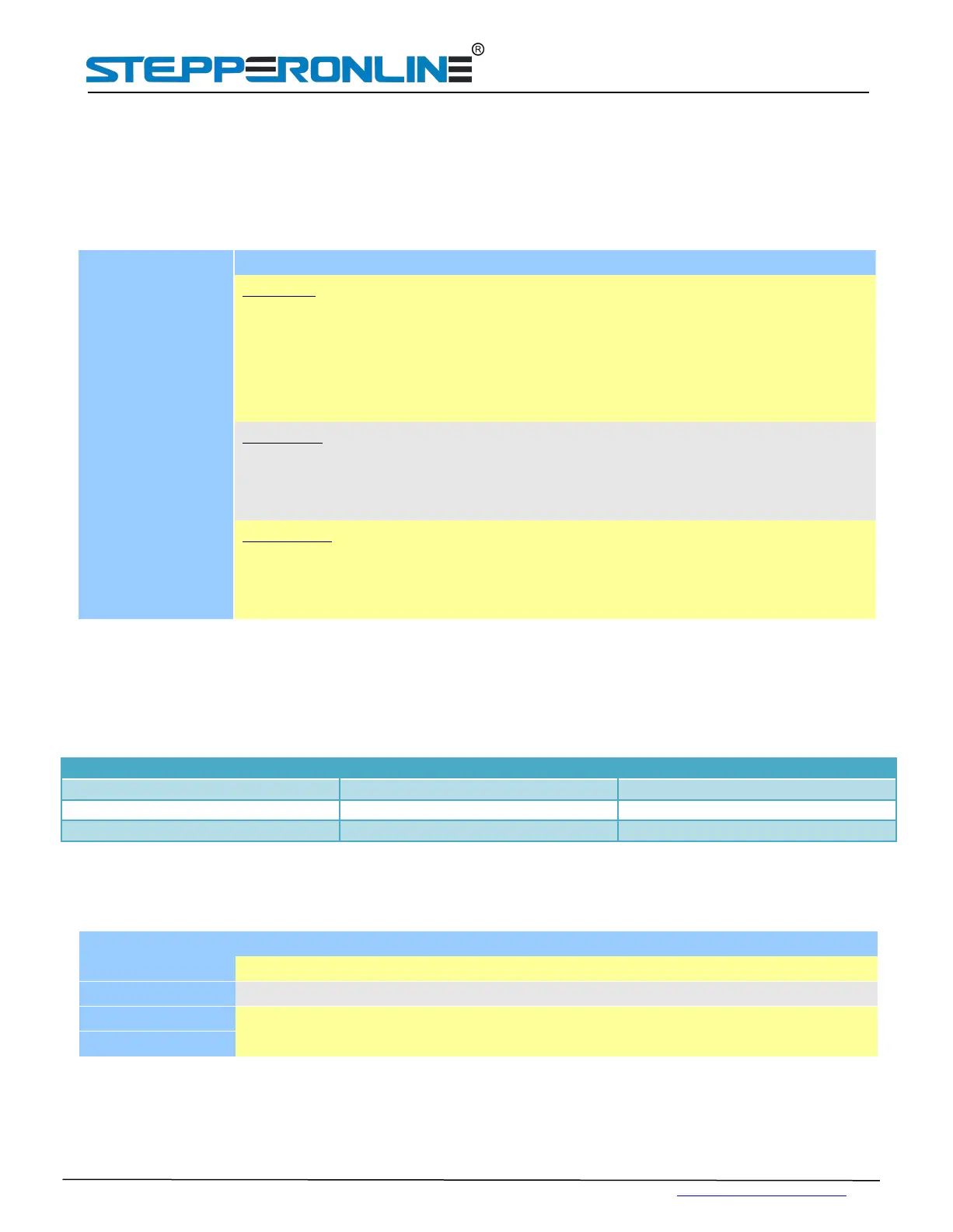
Connector P1 Configurations
DIRsignal: In single-pulse mode, this signal has low/high voltage levels, representing two
directions of motor rotation; in CW/CCW mode (set by inside jumper J3), this signal is
counter-clock (CCW) pulse. For reliable motion response, DIR signal should be ahead of PUL
signal by 5μs at least. 4-5V when DIR-HIGH, 0-0.5V when DIR-LOW. Please note that
rotation direction is also related to motor-drive wiring match. Exchanging the connection of
two wires for a coil to the drive will reverse motion direction.
Pulse signal: In single pulse (pulse/direction) mode, this input represents pulse signal, each
rising edge active ; 4-5V when PUL-HIGH, 0-0.5V when PUL-LOW. In CCW mode (set by
inside jumper J3), this input represents clockwise (CW) pulse. For reliable response, pulse
width should be longer than 2.5μs.
Enablesignal: This signal is used for enabling/disabling the drive. High level (NPN control
signal, PNP and differential control signals are on the contrary, namely low level for enabling.)
for enabling the drive and low level for disabling the drive. Usually left UNCONNECTED
(ENABLED).
Selecting Valid Pulse Edge,Direction and Control Signal Mode
There are three jumpers J1,J2 and J3 inside the DM860T specifically for selecting control mode, direction a n d v a l i d
p u l s e e d g e , as shown in figure 2. Default setting are t h a t J1 is s h o r t ci r c u i t and J2 J3 are open circuit . (Note:
a short circuit jumper.is in reserve )
Figure 2:J1,J2 and J3 jumper Settings
Connector P2 Configurations
Pin Function Details
A+, A- Motor Phase A
B+, B- Motor Phase B
AC
Power supply, 18~80VAC , Including voltage fluctuation and EMF voltage.
AC