10
ELECTRICAL CONNECTIONS (continued)
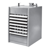
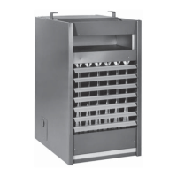
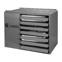
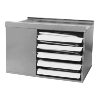
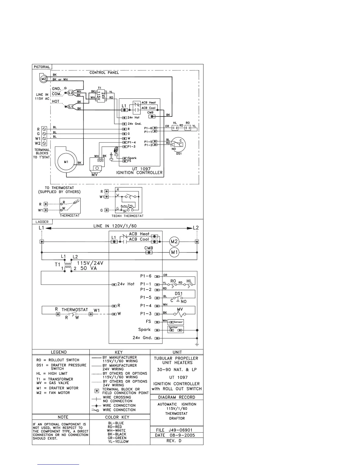
Figure 9 - Tubular Propeller Units Equipped with a Rollout Switch
Tubular 30 thru 90 Unit Sizes with Natural and Propane (LP) Gas
NOTICE: See Figures 7, 8 and 9 for
connecting the thermostat to the unit
heater. If using a standard low voltage
thermostat with a sub-base switch for
fan control, remove the jumper between
G and R. Connect the G terminal of the
thermostat to the G terminal of the unit
heater.