Do you have a question about the Sterling QVF 60 and is the answer not in the manual?
Instructions for responding to gas leaks, including ventilation and contacting the gas supplier.
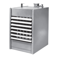
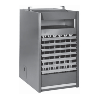
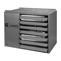
An overview of the unit heater's design and intended use as a low static pressure propeller fan heater.
Details on unit performance metrics, dimensions, clearances, and heat throw distances.
References to national and local codes governing the installation of gas unit heaters.
Important warnings and cautions regarding safe operation, maintenance, and potential hazards.
Guidelines for selecting appropriate locations for unit heater installation, considering safety and performance.
Required minimum distances from combustible materials, walls, and ceilings for safe installation.
Requirements for providing adequate air for proper combustion and ventilation.
Instructions and considerations for securely mounting the unit heater to ceilings or structures.
Guidance on sizing and connecting the gas supply line to the unit heater.
Detailed steps and safety precautions for installing gas piping and making connections.
Procedures and requirements for safely venting combustion byproducts from the unit heater.
Guidance on proper thermostat placement and wiring for effective temperature control.
Instructions for setting the heat anticipator to match the unit's amperage draw for optimal performance.
Information about the fan control relay, its function, and start-up delay limitations.
Description of the combination gas control valve, limit switch, fan switch, and thermostat functions.
Step-by-step instructions for safely lighting the pilot and starting the unit heater.
Procedure for safely turning off the unit heater and its electrical supply.
Details on the dual automatic gas valve, electric ignition, limit switch, and fan switch.
Instructions for starting the unit with an intermittent pilot ignition system, including burner ignition.
Steps to safely turn off the unit heater and its electrical power.
Procedure for adjusting the primary air shutter for optimal burner flame appearance.
Steps to adjust the pilot flame for a proper, steady flame size.
Instructions for adjusting manifold gas pressure to ensure optimal burner performance.
Diagram and list of components related to the fan and motor assembly.
Diagram illustrating key internal parts like the heat exchanger and draft diverter.
Diagram showing individual components of the burner assembly, including manifold and pilot.
Checklist of pre-start-up inspections required before operating the gas equipment.
Essential checks to perform with power and gas off, covering mechanical and electrical connections.
Tests to conduct with power and gas on, including ignition, pressure, and limit cycle checks.
Procedures for verifying blower operation, voltage, amperage, and RPM.
| Brand | Sterling |
|---|---|
| Model | QVF 60 |
| Category | Gas Heater |
| Language | English |