Do you have a question about the Sterling QVF 75 and is the answer not in the manual?
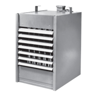
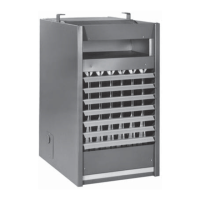
Provides a general overview of the gas unit heater's design and purpose, highlighting its low static pressure and propeller fan features.
Details technical performance metrics, including BTU/hr output, thermal efficiency, and air velocity for various unit sizes.
Outlines mandatory installation adherence to national and local building codes, including ANSI and NFPA standards.
Highlights critical safety measures for installation and operation, such as proper grounding, fuel usage, and avoiding hazardous locations.
Provides guidelines for selecting appropriate locations for unit heater installation, considering clearances and air circulation needs.
Specifies minimum required distances from combustible materials, walls, and ceilings for safe unit heater installation.
Details requirements for providing adequate air for combustion and ventilation in the installation space.
Guides on securely mounting unit heaters using appropriate hardware, emphasizing structural support and level installation.
Explains how to size and install gas piping to ensure adequate gas pressure delivery to the unit heater.
Covers the proper procedures for installing gas piping, including pressure testing, support, and connection to the unit.
Details the critical requirements for venting the unit heater, including pipe sizing, slope, and protection from blockages.
Details the correct placement and wiring of the thermostat for optimal heater operation, avoiding adverse environmental factors.
Explains how to set the heat anticipator on the thermostat to match the unit's amperage draw for accurate temperature control.
Describes the function of the fan time delay relay, including its start-up delay and operational rating.
Details the function of each control component, including the gas control valve, limit switch, fan switch, and thermostat.
Provides step-by-step instructions for safely lighting the pilot and initiating the unit heater's operation.
Outlines the procedure for safely turning off the unit heater, including disabling gas and electrical power.
Explains the controls for units with dual automatic gas valves and electric ignition, including pilot solenoid and main gas valve functions.
Guides on starting units with spark ignition, including purging lines, checking gas leaks, and verifying burner ignition.
Details the process for shutting down spark ignition units, involving turning off gas and electrical power.
Instructs on adjusting the primary air shutter to achieve optimal flame characteristics by preventing yellow tipping.
Outlines routine inspections, cleaning of burners, heat exchanger, and fan section, plus safety checks.
Covers procedures for adjusting pilot flame size and manifold pressure for optimal burner performance.
Advises on fan motor lubrication based on operating hours and cleaning fan blades and guards.
Lists and illustrates components related to the propeller assembly, including motor, fan guard, and fan blade.
Identifies key internal parts of the heater, such as the heat exchanger, draft diverter, and blocked vent switch location.
Shows and labels components of the burner assembly, including manifold, pilot tubing, and thermocouple location.
Checklist for verifying installation status and understanding controls before starting the equipment, with power and gas off.
Pre-start checks with power and gas off, focusing on physical condition, connections, and component security.
Post-start checks with power and gas on, verifying gas pressure, ignition, safety controls, and operational parameters.
| Brand | Sterling |
|---|---|
| Model | QVF 75 |
| Category | Gas Heater |
| Language | English |