Do you have a question about the Sterling QVF 175 and is the answer not in the manual?
Installer must inspect and correct any issues during shipment or installation.
Inspect unit immediately for any damage that occurred during shipment.
Essential warnings cover installation, operation, fuel, grounding, and environmental hazards.
Specifies minimum mounting heights and clearances from combustible materials.
Guidelines for aircraft hangars, public garages, and parking structures.
Directs airflow to areas of maximum heat loss, avoiding obstructions.
Details air needs for combustion and requirements for tight buildings.
Instructions for determining gas pipe size based on input and length, and managing pressure.
Procedures for connecting gas piping, including shutoff valves and test ports.
Essential safety and installation guidelines for proper venting of flue gases.
Guidance on mounting and wiring thermostats for optimal control.
Instructions for setting heat anticipators and fan time delay controls.
Describes the functions of the gas control valve, limit switch, and fan switch.
Step-by-step instructions for safely lighting the pilot burner and starting the unit.
Procedure for safely turning off the unit heater.
Details the dual automatic gas valve and electric ignition system.
Steps for starting the unit using the spark ignition system.
How to calculate and verify the unit's gas input rate.
Procedure for adjusting the air shutter for optimal burner flame.
Guides for adjusting pilot flame size and manifold gas pressure.
Steps for cleaning, inspection, and servicing the unit's components.
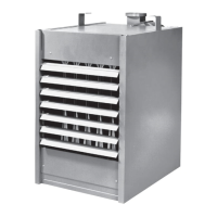
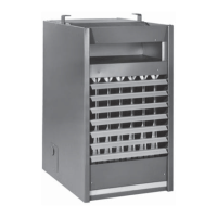
Visual identification of key unit parts and assemblies through diagrams.
Lists common operational issues and their solutions for gas unit heaters.
Information required to order replacement parts from the manufacturer.
Details the terms and conditions of the product's limited warranty.
Ensures the unit is ready for operation with power and gas off.
Verifies proper operation of heating functions and the blower with power and gas on.
| Brand | Sterling |
|---|---|
| Model | QVF 175 |
| Category | Gas Heater |
| Language | English |