Do you have a question about the Sterling QVF 250 and is the answer not in the manual?
Provides critical safety advice regarding gas leaks and hazardous conditions.
Installer must inspect and correct any problems found after shipment and installation.
Inspect shipment immediately for damage and file claim if necessary.
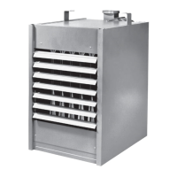
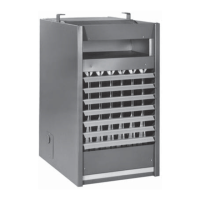
Factory assembled, low static pressure propeller fan heater for space heating, not ductwork.
Overview of key specifications including BTU/Hr, dimensions, and clearances.
Details required adherence to local codes and national standards like ANSI Z223.1 and NFPA.
Emphasizes grounding, disconnecting power, and using qualified electricians.
Warns against fuel mixing, alterations, and safe operation in non-hazardous locations.
Table detailing performance metrics like efficiency, airflow, and voltage for various unit sizes.
Table providing physical dimensions and mounting details for different unit sizes.
Specifies minimum clearances and mounting heights for safe and efficient operation.
Specific installation requirements for unit heaters in aircraft hangars and public garages.
Guidance on directing airflow for optimal heat distribution and avoiding obstructions.
Recommends a minimum thermostat setting of 50°F to prevent condensation and corrosion.
Details the need for adequate ventilation and air supply for satisfactory combustion.
Instructions for securely mounting and suspending unit heaters using appropriate hardware.
Method for determining correct gas pipe size based on input and pipe length using provided tables.
Specific notices for propane gas installations, requiring qualified LP gas dealers.
Requirements for installing gas piping, including local codes, pressure testing, and support.
Table specifying required manifold and inlet pressures for natural and propane gas.
Precautions and procedures for proper venting, including vertical runs and avoiding blockages.
Guidance on venting multiple heaters into a common flue and using draft/power venters.
Guidelines for wiring, grounding, and using appropriate circuits and disconnects.
Guidance on thermostat mounting location and wiring for proper operation.
Description of the combination gas control valve, limit switch, fan switch, and thermostat.
Step-by-step guide for lighting the pilot and starting the unit heater.
Lists and illustrates common parts found in the burner drawer assembly.
Identifies control components such as gas valves, limit switches, and pilot assemblies.
Description of dual automatic gas valve and electric ignition device functions.
Step-by-step guide for starting unit heaters with intermittent (spark) pilot ignition.
Lists and illustrates common parts found in the burner drawer assembly for intermittent ignition.
Identifies control components for intermittent pilot ignition systems, including ignitors.
Formula and method to calculate gas input rate based on gas meter readings.
Procedure for adjusting primary air shutters for optimal burner flame and combustion.
Instructions for adjusting the pilot flame to ensure a proper size and steady flame.
Routine inspection and service tasks, including safety checks and component cleaning.
Identification of individual parts for the propeller assembly of the unit heater.
Identification of internal furnace components including heat exchanger and draft diverter.
Illustrations and labels for parts of the burner assembly, including pilot and orifice.
Diagnosing and correcting issues like flame lifting from burner ports and flames popping back.
Troubleshooting causes and solutions for noisy flames and yellow tipping in burner flames.
Addressing gas odor issues and causes of delayed ignition in the burner system.
Resolving issues like water vapor condensation and rapid burner cycling.
Diagnosing and fixing unit noise problems and pilot ignition failures.
Troubleshooting problems with the fan not running, cycling, or not stopping.
Addressing insufficient heat, too much heat, and cold air delivery.
Resolving cold air delivery, no spark, and spark present but no pilot light.
Diagnosing pilot light failures and hi-limit switch tripping.
Information on providing necessary details when ordering replacement parts.
Details the limited warranty coverage, exclusions, and conditions for gas-fired unit heaters.
Checklist for pre-inspection before powering and starting the gas equipment.
Performing general and gas heating checks with power and gas on.
| Category | Gas Heater |
|---|---|
| Fuel Type | Natural Gas or Propane |
| BTU Input | 250, 000 BTU |
| Ignition Type | Electronic |
| Model | Sterling QVF 250 |