INSTALLATION
ZĤ¼êÐ|ŒêĒĉ
www.stiebel-eltron-usa.com CON Premium | 13
ENGLISH
15.2 Data table
CON 100-1
Premium
CON 150-1
Premium
CON 100-2
Premium
CON 150-2
Premium
CON 200-2
Premium
CON 300-2
Premium
Item number 202025 202026 202027 202028 202029 202030
Electrical data
Power supply - 50/60 Hz single phase single phase single phase single phase single phase single phase
Voltage 120 V 120 V 240 V 208 V 240 V 208 V 240 V 208 V 240 V 208 V
Wattage 1000 W 1500 W 1000 W 750 W 1500 W 1125 W 2000 W 1500 W 3000 W 2250 W
Btu/hr 3412 5118 3412 2559 5118 3839 6824 5118 10236 7677
Amperage 8.3 A 12.5 A 4.2 A 3.6 A 6.3 A 5.4 A 8.3 A 7.2 A 12.5 A 10.8 A
Required circuit breaker size
1
15 A 15 A 10 A 10 A 10 A 10 A 15 A 15 A 15 A 15 A
Required wire size
1
14 AWG 14 AWG 14 AWG 14 AWG 14 AWG 14 AWG 14 AWG 14 AWG 14 AWG 14 AWG
Electrical connection Power cord with
plug
Power cord with
plug
Junction box, rear Junction box, rear Junction box, rear Junction box, rear
Dimensions
Height 18½˝ (470 mm) 18½˝ (470 mm) 18½˝ (470 mm) 18½˝ (470 mm) 18½˝ (470 mm) 18½˝ (470 mm)
Width 18½˝ (470 mm) 24
5
/
8
˝ (625 mm) 18½˝ (470 mm) 24
5
/
8
˝ (625 mm) 30¾˝ (780 mm) 42
7
/
8
˝ (1090 mm)
Depth 4
15
/
16
˝ (126 mm) 4
15
/
16
˝ (126 mm) 4
15
/
16
˝ (126 mm) 4
15
/
16
˝ (126 mm) 4
15
/
16
˝ (126 mm) 4
15
/
16
˝ (126 mm)
Weights
Weight 13.0 lb (5.9 kg) 16.5 lb (7.5 kg) 13.0 lb (5.9 kg) 16.5 lb (7.5 kg) 22.5 lb (10.2 kg) 27.8 lb (12.6 kg)
Other data
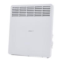
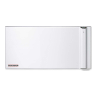
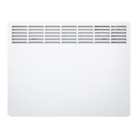
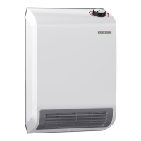
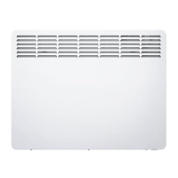
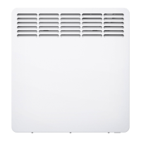
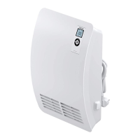
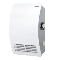
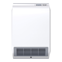
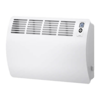
Type Wall mounted convection heater
Color Alpine white
Settings
Temperature range 41-86 °F (5-30 °C)
Frost protection setting 45 °F (7 °C)
1
This is our recommendation as the manufacturer. Check local codes for compliance if necessary.
15.3 Wiring diagrams
15.3.1 120 V wiring diagram for CON 100-1, CON 150-1 Premium
LN
GND
L L1
N
8pol.
Rt - Sensor
UI User Interface
R1
FSH FSH/FSV
FSH
FSH
FSH
FSH
A1 = Power PCBA
S1
N1
A2
(Z1) (Z2) (Z3)
15.3.2 208–240 V wiring diagram for CON 100-2, CON 150-2,
CON 200-2, CON 300-2
L1 L2
GND
L L1
N
8pol.
Rt - Sensor
UI User Interface
R1
FSH FSH/FSV
FSH
FSH
FSH
FSH
A1 = Power PCBA
S1
N1
A2
(Z1) (Z2) (Z3)
 Loading...