www.stiebel-eltron.com DCE 11/13| DCE 11/13 RC| DCE 11/13 H | 31
INSTALLATION
Specication
16. Specification
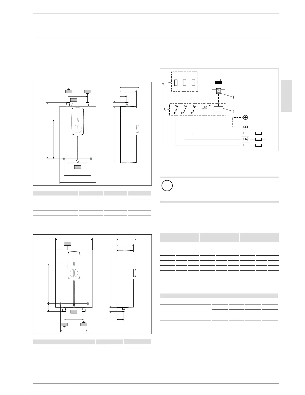
16.1 Dimensions and connections
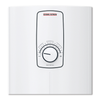
DCE11/13 | DCE11/13RC
293
188
85
99
35
19
b02
b03
c01
c06
193
291
140
D0000039746
DCE 11/13 DCE 11/13 RC
b02 Entry for cables I
b03 Entry for cables II
c01 Cold water inlet Male thread G 3/8 A G 3/8 A
c06 DHW outlet Male thread G 3/8 A G 3/8 A
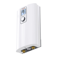
DCE 11/13 H
293
85
99
35
19
b02
b03
100
140
c01
c06
193
40
188
D0000050396
DCE 11/13 H
b02 Entry for cables I
b03 Entry for cables II
c01 Cold water inlet Male thread G 1/2 A
c06 DHW outlet Male thread G 1/2 A
16.2 Wiring diagram
3/PE ~ 380-415 V
D0000040233
3
4
1
2
1 High limit safety cut-out
2 Electronic safety switch
3 PCB
4 Heating system
!
Material losses
In the case of a permanent power supply, connect
the power cable according to the designations on
the socket terminals.
16.3 Application areas / conversion table
Specific electrical resistance and specific electrical conductivity
(see chapter "Installation/ Specification/ Data table").
Standard specification at
15°C
20°C
25°C
Spec. re-
sistance
ρ ≥
Spec. conduc-
tivity σ ≤
Spec. re-
sistance
ρ ≥
Spec. conduc-
tivity σ ≤
Spec. re-
sistance
ρ ≥
Spec. conduc-
tivity σ ≤
Ωcm mS/m μS/cm Ωcm mS/m μS/cm Ωcm mS/m μS/cm
900 111 1111 800 125 1250 735 136 1361
1100 91 909 970 103 1031 895 112 1117
Outlet temperature approx. 60°C for the kitchen sink and when
using a thermostatic valve
Outlet volume
Appliance kW 11 13.5
Cold water inlet temperature
6°C l/min 2.9 3.6
10°C l/min 3.2 3.9
14°C l/min 3.4 4.2
 Loading...