14
Fig. 3
7046.01
DHC 3, DHC 4, DHC 6, DHC 6 S, DHC 8
17
18
19
20
21
22
23
24
25
26
27
29
Installation
instructions
(for the qualified installer)
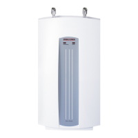
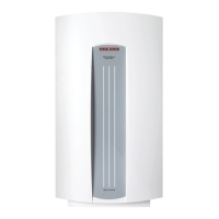
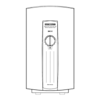
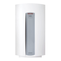
Composition of the unit (Fig. 3)
Under-sink installation
DHC 3 U, DHC 6 U, DHC 6 S
1 Hot water connection G 3/8 *
2 Cold water connection G 3/8 *
3 Thermostat
4 Overheating light
5 Power light
6 Safety thermal cut-out with reset
button
7 Differential pressure switch
8 Flow rate adjustment screw
9 Terminal strip
10 Rear wall
11 Strain relief unit (only DHC 3 U)
12 Connection cable with plug, 800 mm
long (only DHC 3 U, enclosed)
13 Jet regulator for fitting (only DHC 3 U,
enclosed)
14 Cover
15 Function diaphragm
16 Heating system
* The connection pipe for the DHC 6 S
must be connected during installation.
Over-sink installation
DHC 3, DHC 4, DHC 6, DHC 6 S,
DHC 8
17 Terminal strip
18 Overheating light
19 Power light
20 Safety thermal cut-out with reset
button
21 Differential pressure switch
22 Flow rate adjustment screw
23 Rear wall
24 Cold water connection G 1/2, can be
used for surface installation and
concealed installation
25 Hot water connection G 1/2, can be
used for surface installation and
concealed installation
26 Cover
27 Function diaphragm
28 Heating system
29 Thermostat
Important note
All the information in these
Installation and Operating
Instructions must be followed carefully.
These Instructions provide important
details regarding safety, operation,
installation, and maintenance of the unit.
24
25
28
DHC 3 U, DHC 6 U, DHC 6 S
7045.02
1
2
3
4
5
6
7
8
9
10
11
12
13
14
15
16
 Loading...