16
264 mm
7047.02
12
3
4
6
7
8
99
100 mm
100 mm
G 1/2
104 mm
G 1/2
G 3/8
50 mm
9 mm
280 mm59 mm
270 mm
360 mm
11
10
5
200 mm
35 mm
12 mm 65 mm
Legend to Fig. 5
Connection dimensions in mm.
1 Hot water connection DHC 3 U,
DHC 6 U, DHC 6 S
2 Cold water connection DHC 3 U,
DHC 6 U, DHC 6 S
3 Hot water connection, DHC,
concealed
4 Cold water connection, DHC,
concealed
5 Hot water connection, DHC, above
work surface
6 Cold water connection, DHC,
above work surface
7 Electrical connection DHC 3 U,
with connection cable and mains
plug enclosed with the unit
DHC 6 U connection cable to be
provided by client.
8 Electrical connection concealed
(DHC)
9 Electrical connection above work
surface (DHC)
10, 11 Securing holes
Fig. 5
Fig. 7
7049.01
Fig. 6
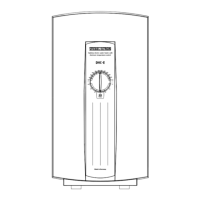
Legend to Fig. 6
13-17 Marked connection apertures in unit
rear wall
13 Electrical connection, top
14 Electrical connection, bottom
(aperture for Item 20 also)
15 Water connection, concealed
16 Water connection, above work
surface
17 Water connection DHC 6 S
Preparing to install the unit
– Release securing screw (Item 17).
– Remove unit cover (Item 18).
– DHC 3, DHC 4, DHC 6, DHC 8
– Break through cable conduits
Installation from above: Item 13
Installation from below: Item 14
– Break apertures for water
connections:
Concealed Item 15
Exposed Item 16.
– DHC 6 S - under-sink installation
– Break through cable conduits
Installation from above: Item 13
Installation from below: Item 14
– Break apertures for water
connections Item 15 and 17.
7048.01
20
18
7050.01
13
14
15
15
16
16
19
17
 Loading...