14
2.6 Installation location
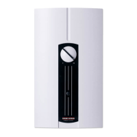
The DHF ... C compact control is to
be installed vertically in accordance
with
A
(over-sink or under-sink) in a
closed, frost-free room, as near as possible
to the tap point (a dismantled unit is to be
stored in frost-free conditions, since resi-
dual water always remains in the unit).
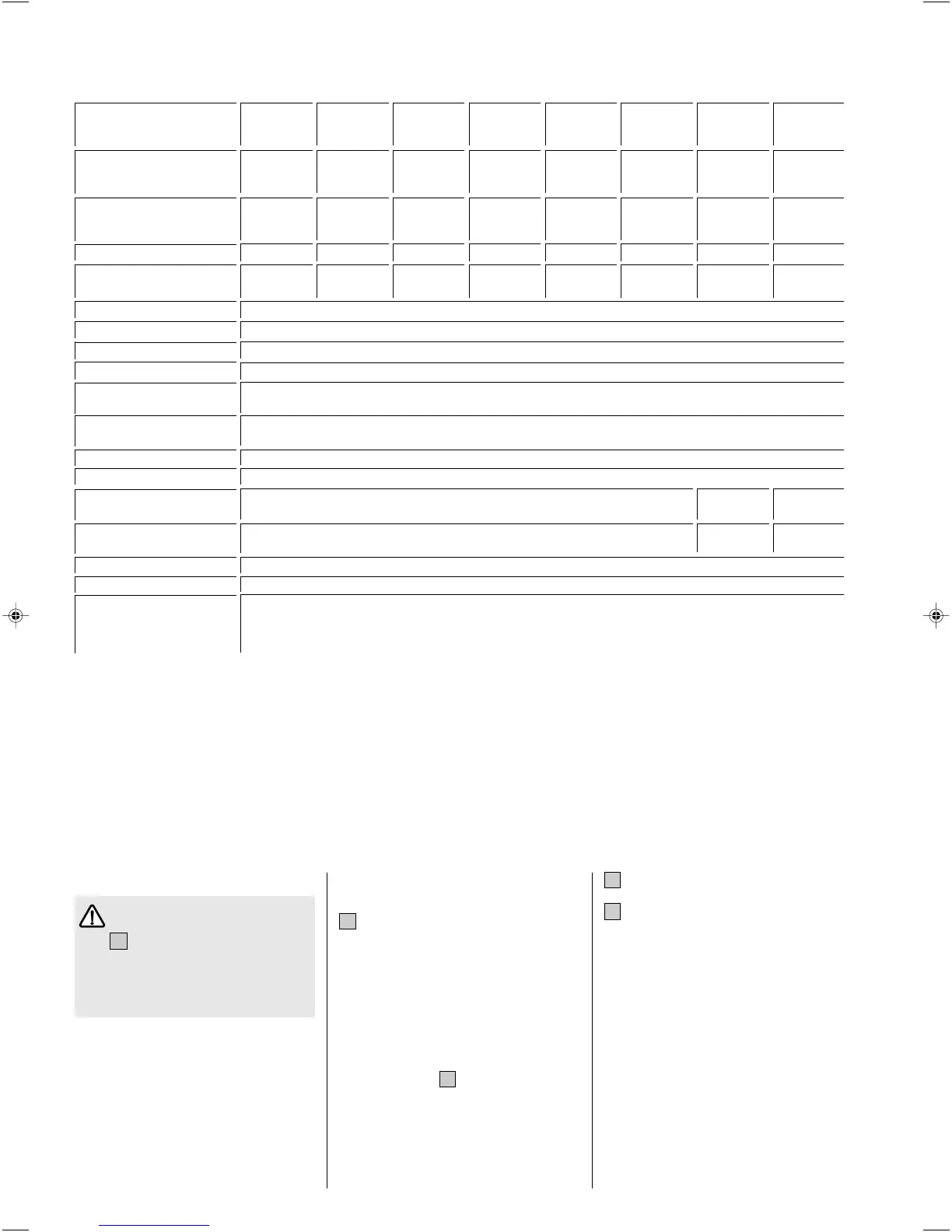
2.5 Technical data (the data on the unit rating plate are applicable)
2.7 Preparing for unit instal-
lation
B
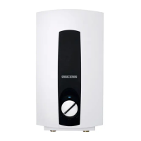
Turn locking cap (3) to the left and with-
draw.
Unscrew cover securing screw and re-
move device cover.
– Detach mounting bracket (19) from the
unit.
– Thoroughly flush through the cold water
supply pipe.
– In the case of a replacement installation,
the available cold water 3-way three-way
isolating valve (
D
, 6) can if necessary be
used.
– With the help of the template (separate
this from the operating and installation
instructions), determine the position of
the cable entry (concealed connection)
and the mounting bracket (19).
G
Cut the electrical connection cable to
length and strip.
C
Secure the mounting bracket.
When replacing DHF/DHA old models
(height 370 mm), the available drilled
securing holes (20) can be used.
– Secure the unit to mounting bracket with
the screwed sleeve (14). Using the nut
on the threaded bolt (21), unevennesses
in the wall, caused for example by mis-
aligned tiles, can be compensated for
(maximum 12 mm).
Table 3
* Pressure drop values also apply to the minimum flow pressure in accordance with DIN 44851 / Flow rate for heating from 10 °C to 55 °C
(∆ ϑ 45 K). A pressure drop of 0.1 MPa (1 bar) is recommended for pipe network dimensioning, in line with DIN 1988 Part 3, Table 4.
Electrical connection 3/PE ~ 400 V 1/N/PE ~ 3/PE ~ 230 V
220/230 V
Max. system-impedance
Z max
to DIN EN 61000-3-11 Ω 0.14
Protection mode to
DIN EN 60529 IP 24
Type DHF 13 C DHF 13 C-A DHF 15 C DHF 18 C DHF 21 C DHF 24 C DHF 12 C1 DHF 13 C3
compact compact compact compact compact compact compact compact
control control control control control control control control
Heat output V 400 400 400 400 400 400 220 230 230
Partial power Stage z kW 6.6 6.6 7.5 9 10.5 12 8 8.8 6.6
Rated power Stage zz kW 13.2 13.2 15 18 21 24 12 13.2 13.2
Min. flow rate to activate unit
Stage z l/min 2.5 3.0 3.0 3.9 4.4 4.9 2.5 2.5
Stage zz l/min 3.7 4.5 4.5 5.9 6.4 7.6 3.7 3.7
Flow rate limiter l/min 4.5 6.5 6.5 7.0 7.5 8.0 4.5 4.5
Pressure loss * MPa 0.05 0.055 0.055 0.06 0.06 0.07 0.05 0.05
Flow rate l/min 3.7 4.5 4.5 5.9 6.4 7.6 3.7 3.7
Nominal water volume l 0.6
Type of construction Closed
Rated overpressure MPa 1 (10 bar)
Weight kg 4.0
Protection class to
DIN EN 60335 1
Test mark See unit rating plate
Water connection G ½ (external thread)
Heating element Copper tubular heating element
Cold water inlet ≤ 20 °C
Use in waters
Total alkaline earths ≤ 2.5 mol/m³
Overall hardness (earlier unit) ≤ 14 °d
Hardness range (earlier unit) Inclusive of 2 (medium hard)
169640-34494-8238 DHF 12-24 C1.pmd 26.03.2007, 15:2214
 Loading...