22 |DHF-C www.stiebel-eltron.com
INSTALLATION
Safety
INSTALLATION
7. Safety
Only a qualified contractor should carry out installation, commis-
sioning, maintenance and repair of the appliance.
7.1 General safety instructions
We guarantee trouble-free function and operational reliability only
if original accessories and spare parts intended for the appliance
are used.
!
Material losses
Observe the maximum inlet temperature. Higher tem-
peratures may damage the appliance. You can limit the
maximum inlet temperature by installing a central ther-
mostatic valve.
7.2 Instructions, standards and regulations
Note
Observe all applicable national and regional regulations
and instructions.
Protection rating IP 24 (splashproof) can only be guaranteed with
a correctly fitted cable grommet.
8. Appliance description
8.1 Standard delivery
The following are delivered with the appliance:
- Wall mounting bracket
- Installation template
- 2 twin connectors
- Cross-piece
- Tee
- Flat gaskets
- Strainer
- Plastic profile washer
- 2 cover guides (for installation on finished walls)
8.2 Accessories
Taps/valves
- MEKD - kitchen pressure tap
- MEBD - bath pressure tap
Plug G½A
The plugs are required if you use any taps other than the pressure
taps for finished walls recommended in the accessories.
Installation set for finished walls
- Solder fitting - copper pipe for solder connection Ø12mm
- Compression fitting - copper pipe
- Compression fitting - plastic pipe (suitable for Viega: San-
fix-Plus or Sanfix-Fosta)
Universal mounting frame
Mounting frame with electrical connections.
Load shedding relay (LR 1-A)
The load shedding relay for installation in the distribution board
provides priority control for the instantaneous water heater when
other appliances, such as electric storage heaters, are simultane-
ously being operated.
9. Preparations
9.1 Installation site
!
Material losses
Install the appliance in a room free from the risk of frost.
Always install the appliance vertically and near the draw-off
point.
The appliance is suitable for undersink and oversink installations.
Note
Mount the appliance on the wall. The wall must have
a sufficient load-bearing capacity.
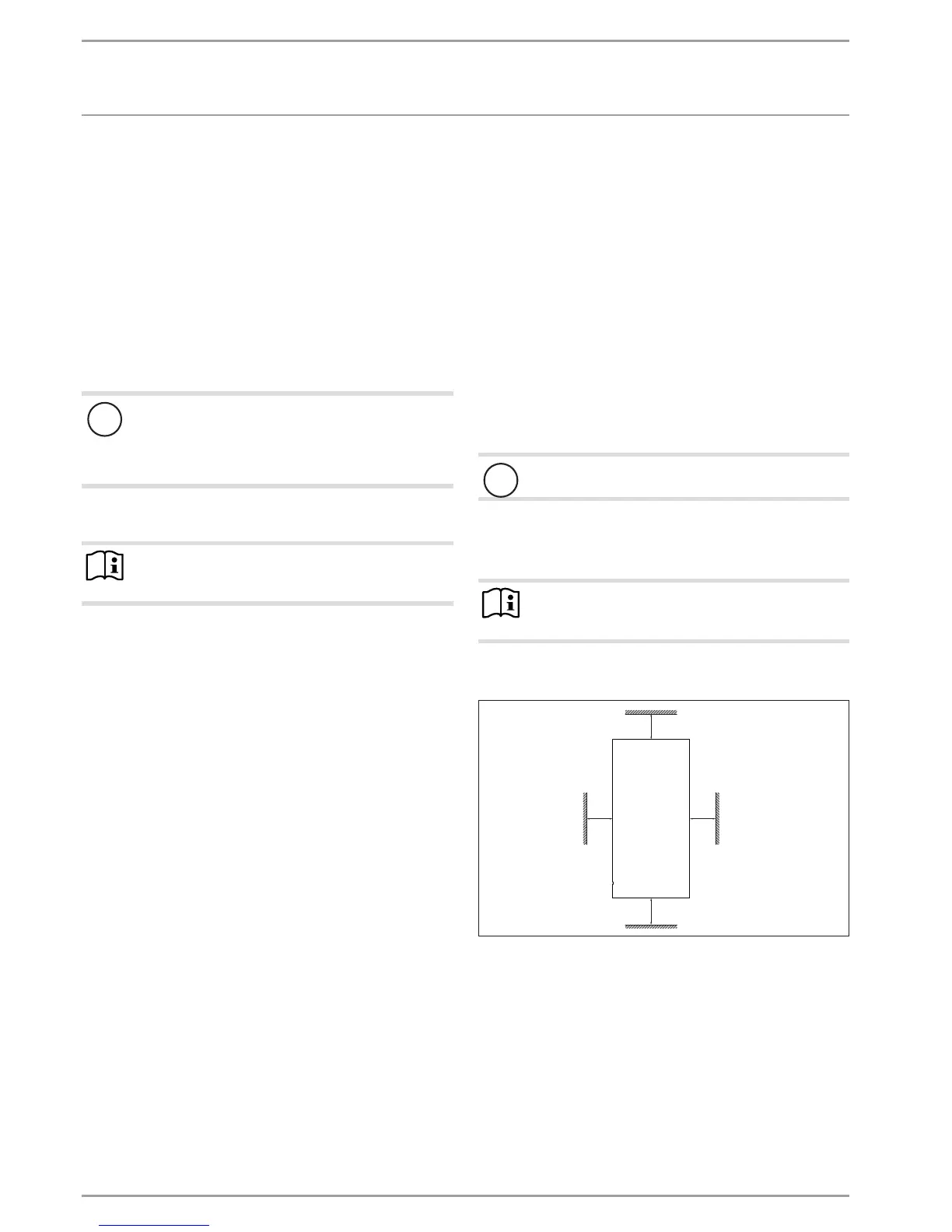
9.2 Minimum clearances
≥50≥50
≥90
≥90
D0000060809
Maintain the minimum clearances to ensure trouble-free op-
eration of the appliance and facilitate maintenance work.
9.3 Water installation
Never operate with preheated water.
Flush the water line thoroughly.
Ensure that the flow rate for switching on the appliance is
achieved (see chapter "Installation/ Specification/ Data
table", On). Increase the mains water pressure if the re-
quired flow rate is not achieved with the draw-off valve fully
opened.
 Loading...