www.stiebel-eltron.com LWZ304-404 SOL | 13
INSTALLATION
Installation
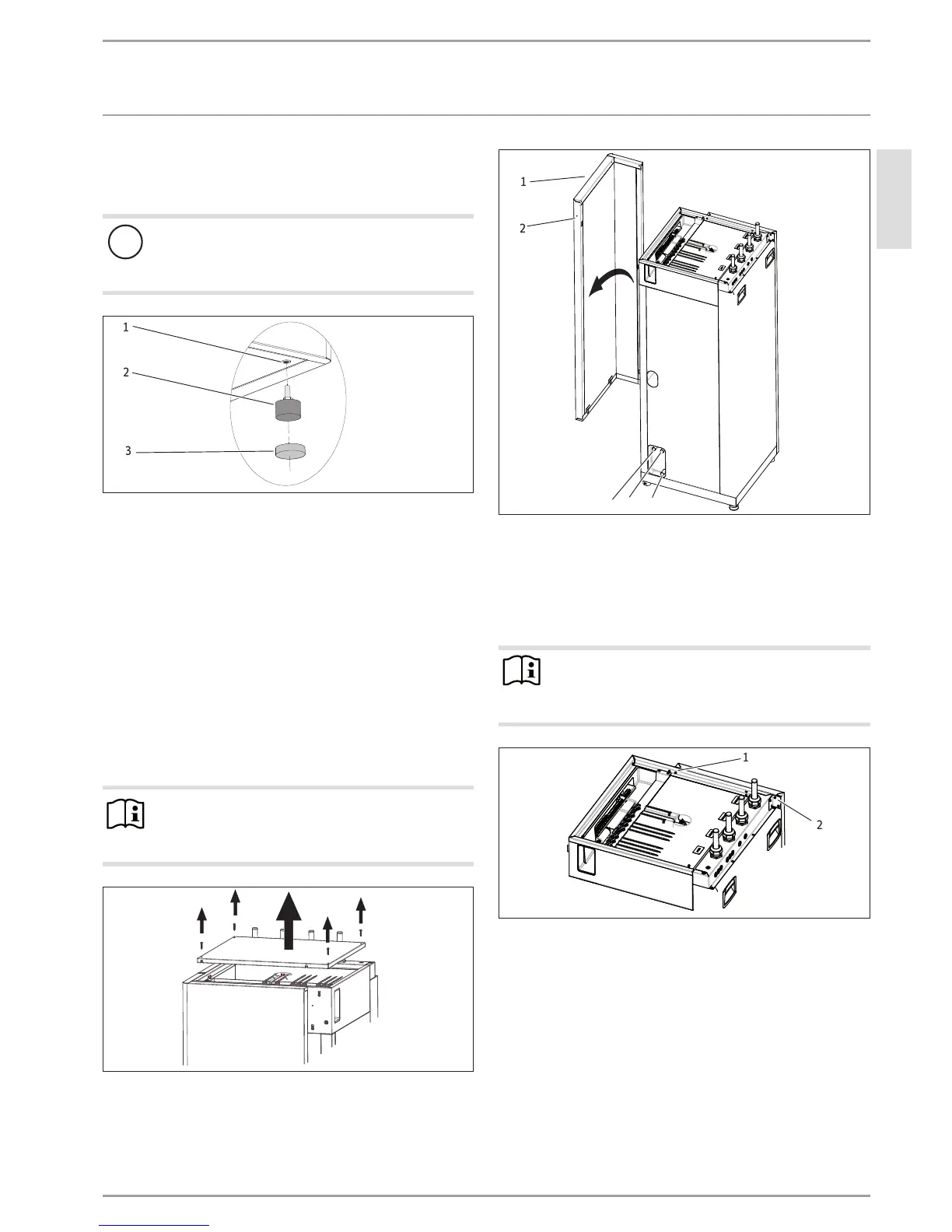
5.2 Installing the cylinder module
Undo the screws underneath the pallet with which the cylin-
der module is secured to the pallet.
!
Material losses
Never tilt the cylinder module excessively. Contacts be-
tween the casing and the floor can damage the paint-
work.
1
2
3
26_04_01_0550
1 Captive nut on the bottom of the cylinder module
2 Adjustable foot with nut for fitting with an open-ended
spanner
3 Sliding block
Carefully tip the cylinder module far enough to enable the
adjustable feet to be inserted.
Insert the adjustable feet into the captive nuts with which the
cylinder module was previously secured to the pallet.
Remove the cylinder module carefully from the pallet.
Push the sliding blocks supplied underneath the adjustable
feet.
Level the cylinder module vertically by turning the height-ad-
justable feet. Arrange the bottom panel so that it is 4 to
5mm higher than the bottom panel of the function module.
This is the amount by which the cylinder module drops when
it is being filled with water.
Note
The adjustable feet must not be fully screwed in, oth-
erwise you will not be able to push the joining bracket
between the bottom panel and the foot.
26_04_01_0552
Undo the cover screws on the cylinder module.
Reach through the port on the r.h. side of the cylinder mod-
ule and push the cylinder module cover upwards.
Remove the cylinder module cover.
26_04_01_0559
1
3
5
4
2
1 Front panel of the cylinder module
2 Screw for securing the front panel
3 DHW flow
4 Heating flow
5 Common return
Lift the front panel of the cylinder module slightly and re-
move it from the cylinder module.
Note
At the factory, the r.h. side of the cylinder module front
panel a screw is fitted, which you later secure the cylinder
module front panel to the fascia frame.
D0000047062
1
2
1 Screw for securing the side panel
2 Angled panel for securing the side panel
Undo the screw and release the angled panel securing the
side panel.
Lift the side panel slightly and remove it from the cylinder
module.
Remove the protective caps from the three pipes (DHW flow,
heating flow, common return); these are located in the lower
section on the r.h. side of the function module. Later on,
these pipes connect the function module and cylinder mod-
ule hydraulically.
 Loading...


