www.stiebel-eltron.com LWZ304-404 SOL | 27
INSTALLATION
Commissioning
If the terminal addresses were not assigned, there would be con-
flicts in communication between the appliance and the program-
ming units, as every programming unit is given the same standard
value for the terminal address parameter.
Assign value 1 to the "TERMINAL ADDRESS" parameter of the first
programming unit. Assign value2 to the "TERMINAL ADDRESS"
parameter of the second external programming unit and value 3 to
the "TERMINAL ADDRESS" of the third external programming unit.
Note
If, before commissioning for the intended use, you want
to dry out or heat the building, continue with the follow-
ing chapter; otherwise with chapter "Commissioning for
the intended operation".
6.2.1 Commissioning for drying out or heating
Note
During drying out, the evaporator can ice up and con-
densate can form on the housing parts.
Isolate all poles of the compressor and electric emergency/
booster heater from the power supply by tripping their MCBs.
Open the thermostatic valves or zone valves of all radiators
and/or heating circuits.
Open the automatic air vent valve in the heating circuit and
in the appliance. Automatic air vent valves are located in the
cylinder module as well as in the refrigeration unit at the
pump and the multi function assembly.
Start the appliance using the control unit MCB. Subject to de-
mand, the appliance components (pumps, fans) start.
The tap symbol appears in the display. The appliance is in DHW
heating mode.
After a while, fault F07 is indicated, which shows that the exhaust
air filter has failed. This is normal as the exhaust air filter is sup-
plied via the compressor MCBs/fuses.
Switch manual mode ON.
In the "DHW" menu set the "DHW SET MANUAL" parameter to
10°C.
The appliance switches over to heating mode. The radiator symbol
appears in the display. In this operating mode, the heating circuit
pump should run until no more air noise can be heard.
Switch automatic mode ON.
Shut down the appliance by isolating all poles of all supply
circuits from the mains.
Switch ON the compressor MCBs.
Switch the controller MCBs back ON.
The compressor starts after some time.
Note
Check the exhaust air fan. If the exhaust air fan drags,
switch off the appliance and align the exhaust air fan.
See chapter "Troubleshooting".
Start the dry heating program. Ensure that all radiators or
heating circuits are and remain open.
Once the appliance has operated in the dry heating program
without fault for at least two days you can enable the electric
emergency/booster heater.
To do so, switch on the MCBs for the electric emergency/
booster heater.
If all dusty work has stopped, you can back up the drying process
with ventilation.
Set the fan stage for day mode ("DAY STAGE", P07) to 2.
6.2.2 Commissioning for the intended operation
If the ventilation should not or cannot be operated during the
drying out phase, and the air lines are routed through a cold area,
prevent the ingress of warm moist air into the air lines where it
could condensate.
Before switching on the MCBs, carry out the following checks in
addition to those in chapter"Checks before commissioning":
- Was the heating system vented?
- If an air heating coil is used as the only heating system: Was
the cylinder temperature sensor positioned correctly?
- Has the DHW heating line of the heating circuit been vented?
See chapter "Installation/ Filling and venting the heating
system" on venting the DHW heating line.
Reset the MCBs.
!
Material losses
Check the exhaust air fan. If the exhaust air fan drags,
switch off the appliance and align the exhaust air fan.
See chapter "Troubleshooting".
Using the "HUMIDITY PROTECTION" parameter switch on the
humidity protection function.
6.2.3 Checking the minimum flow rate of the heat sink
The appliance is designed in such a way that no buffer cylinder
is required to provide hydraulic separation of the flow in the heat
pump circuit and the heating circuit in conjunction with area heat-
ing systems.
For installations with several heating circuits, we recommend the
use of a low loss header.
Cooling is only possible in conjunction with a buffer cylinder or
low loss header.
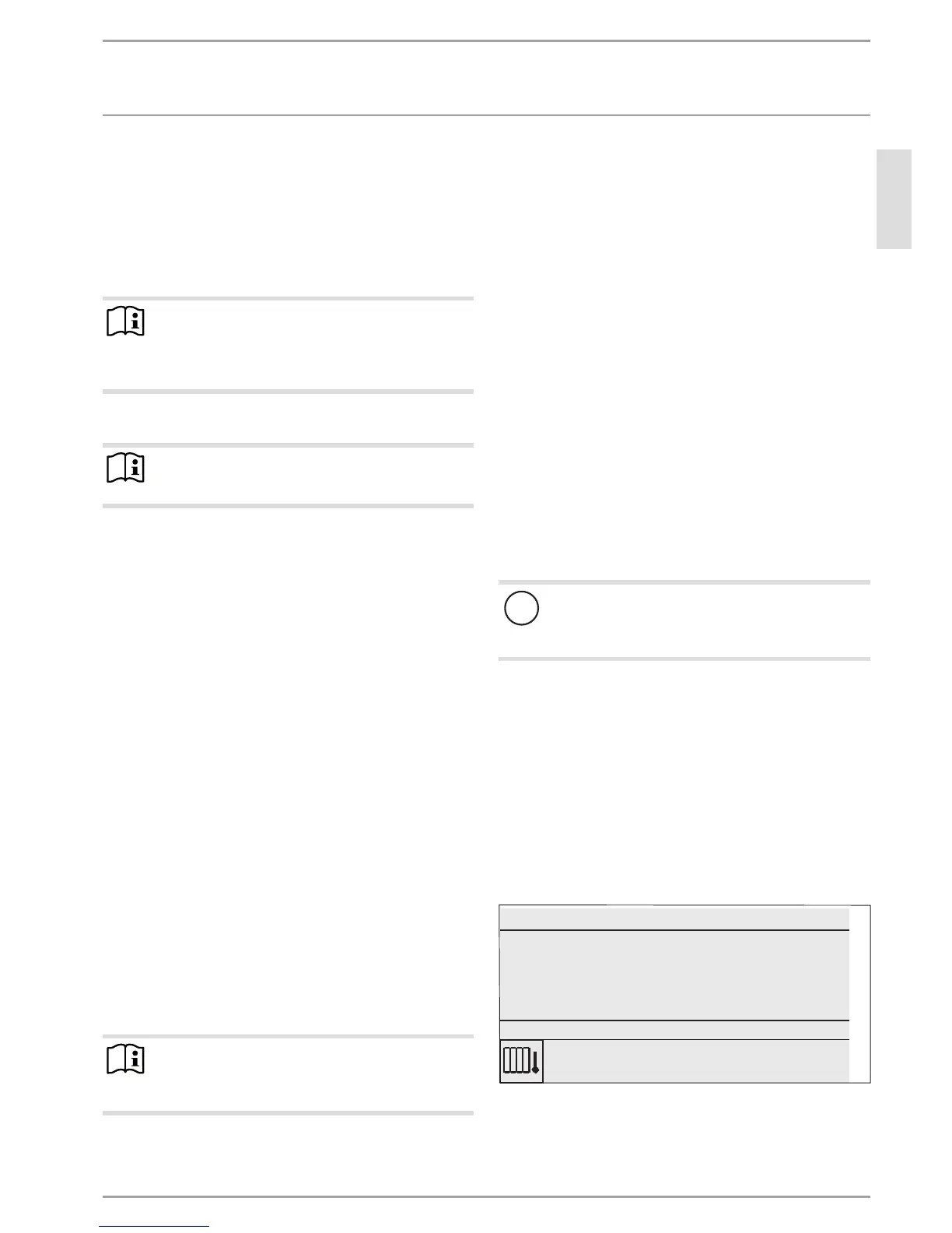
WE D NESDAY 10 SEPT 14
10:23 h
OUTSIDE TEMPERATURE
FLOW R ATE
18.0 °C
0.5 m³/h
50.0 °CDHW TEMPERATURE
MANUAL MODE
26_04_01_0292
In the "FAVOURITES" menu, select the "FLOW RATE"
parameter.
The setting is made in heat pump mode. For this, make the fol-
lowing settings first:
 Loading...


