www.stiebel-eltron.com LWZ304-404 SOL | 9
INSTALLATION
Preparations
4.2 Air routing
Prevent air stream "short circuits". The air intake and discharge
apertures in the external walls should be arranged around cor-
ners. When installing the air intake and discharge apertures on
the same side of the building, maintain a minimum clearance of
at least 2m between apertures. Where that is impossible, create
a separation between the air streams, e.g. by a separating wall or
shrubs between the intake and discharge apertures.
Never align the apertures toward neighbouring living room or
bedroom windows.
4.3 Sound emissions
Sound insulation for rooms adjacent to the installation room
When the appliance is in operation, sound emissions can occur
which may be a nuisance in adjacent rooms. This is especially the
case if the installation room adjoins a living room or bedroom. To
prevent noise pollution, sound attenuation measures are neces-
sary, e.g. sound attenuation of a higher standard for the internal
wall. Pipe fixings and wall outlets must have anti-vibration insu-
lation. For the wall between the installation room and the living
space, we recommend a wall structure that ensures the following
level of sound attenuation:
- 45 dB(A) for adjacent living rooms and bedrooms
- 40 dB(A) for other rooms
Doors should be of sound safety category SK3.
If the appliance backs onto an adjacent room, we recommend the
following level of sound attenuation:
- 55 dB(A) for adjacent living rooms and bedrooms
- 50 dB(A) for other rooms
A passage to the neighbouring room is not recommended.
The floor between the installation room and living areas must
have carefully applied anti-vibration separation. Ensure that no
pipes are routed on or in the wall and that the air ducts have
anti-vibration separation.
If the appliance installation room is included in the building ven-
tilation system, an extract air valve and supply air valve must be
planned in. To avoid the need for an overflow aperture in the
door, the supply air and extract air flow rates must be balanced.
Note
The appliance can seem loud if operated in an unfinished
building without doors. This is because the fixtures and
fittings are not yet in place which will provide sound at-
tenuation; once the building is occupied this should no
longer occur.
Sound attenuation 45dB(A)
Sound attenuation of 45dB(A) can be achieved using, for ex-
ample, a lightweight wall of timber frame construction with full
insulation. The cross-section of the timber supports should be
60x60mm. The wall must have plasterboard panelling on both
sides, with a thickness of 12.5 mm on one side and 10 mm on the
opposite side.
2
1
3
3
2
D0000047127
1 Timber supports 60 x 60 mm
2 Gypsum fibre board 12.5 mm
3 Gypsum fibre board 10 mm
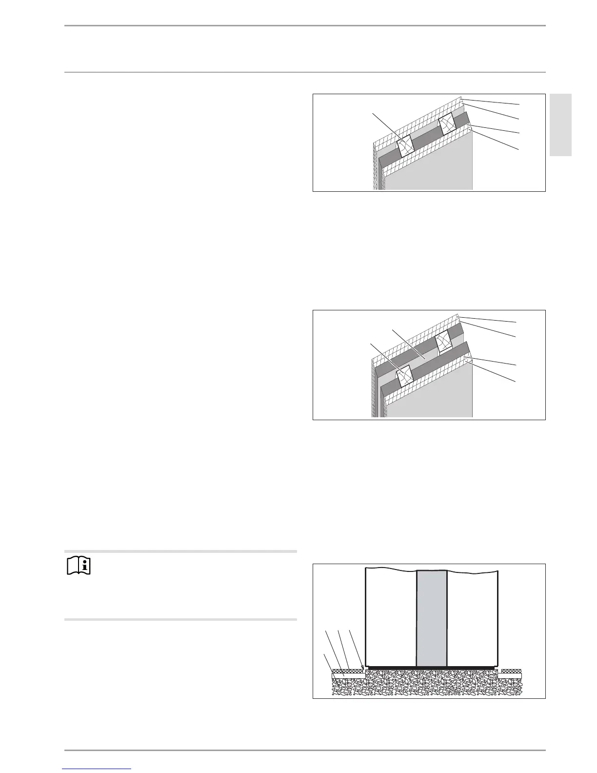
Sound attenuation 55dB(A)
Sound attenuation of 55dB(A) can be achieved using, for exam-
ple, a lightweight twin wall of timber frame construction with
full insulation and 30mm parting line. The cross-section of the
timber supports should be 60x60mm. The wall must have 12.5
mm plasterboard panelling on both sides.
3
1
3
3
3
2
D0000047126
1 Parting line 30 mm
2 Timber supports 60 x 60 mm
3 Gypsum fibre board 12.5 mm
Anti-vibration separation
With the anti-vibration feet, it is possible to install the appliance
on floating screed, as long as this has been applied correctly. If
necessary provide separation.
If the appliance is positioned on a wooden beam ceiling, you must
take special steps to prevent structure-borne noise transmission.
Installation on foundations
3
42
1
26_04_01_0290
1 Concrete base
2 Impact sound insulation
3 Floating screed
4 Screed recess
 Loading...


