28 | LWZ304-404 SOL www.stiebel-eltron.com
INSTALLATION
Settings
Operate the appliance in heating mode. For this, switch the
appliance to "MANUAL MODE", for example. Note down the
previously set value and set the "DHW SET MANUAL" param-
eter to 10°C.
Increase the "MANUAL SET HC" parameter to its maximum
value so that the compressor starts.
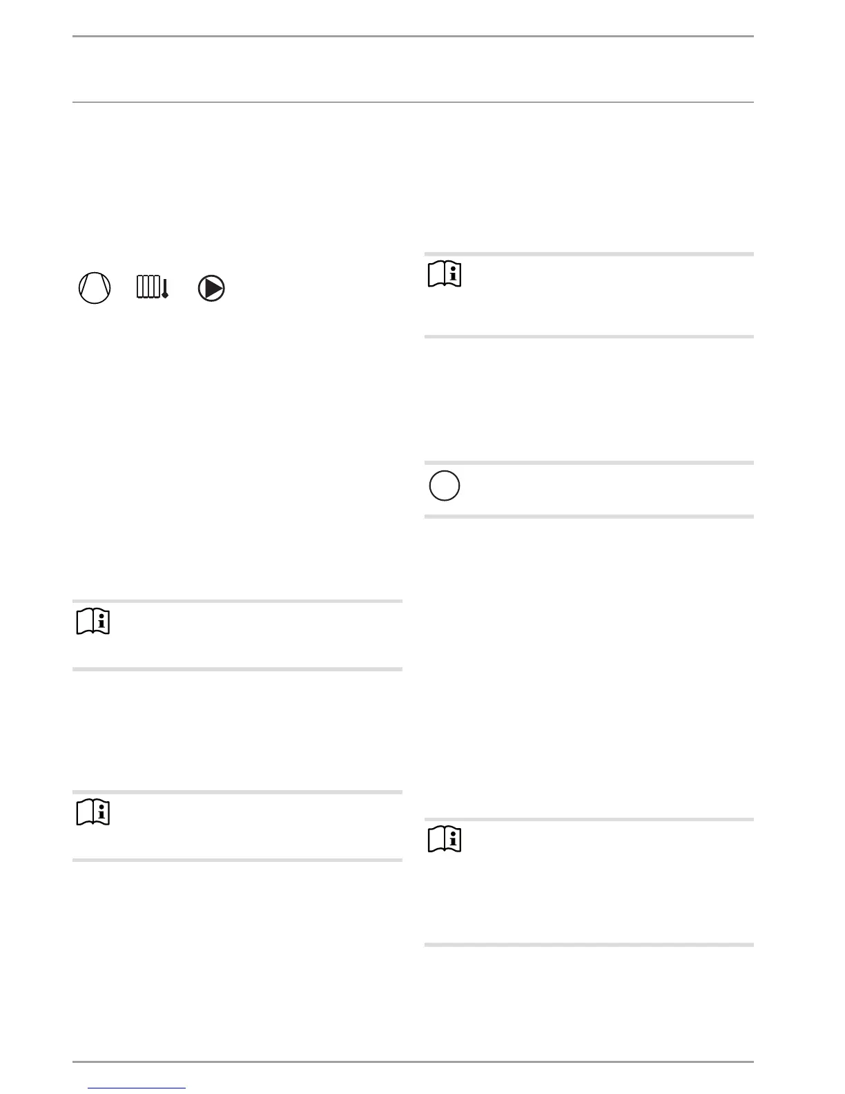
Wait until the appliance has been in operation for at least five
minutes. The display must show the following symbols:
Minimum flow rate without buffer cylinder or low loss header
In such cases, one or more heating circuits in the heating system
must be left open. The open heating circuit(s) should be installed
in the lead room (room in which the external programming unit
is installed, e.g. the living room or bathroom). The lead room
can then be individually controlled by the external FES Comfort
programming unit, indirectly by adjusting the heating curve, or
by activating the room influence.
Fully open the heating circuit(s) in the lead room.
Close all other heating circuits.
If an overflow valve is installed in the heating system, close
this fully before determining the minimum flow rate.
Set the "PUMP SPEED HEATING" parameter so that the mini-
mum flow rate required for the system operation is assured
(see chapter "Specification/ Data table"). You can check the
current flow rate via the value of the previously set favourite
"FLOW RATE".
Note
Never change the "PUMP SPEED DHW" parameter . The
pump speed for DHW operation was optimised at the
factory.
Flow rate with buffer cylinder or low loss header
Set the "PUMP SPEED HEATING" parameter so that the
nominal flow rate required for system operation is assured
(see chapter "Specification/ Data table"). You can check the
current flow rate via the value of the previously set favourite
"FLOW RATE".
Note
Never change the "PUMP SPEED DHW" parameter . The
pump speed for DHW operation was optimised at the
factory.
6.2.4 Completing commissioning
Set all required parameters that you will find in the "COM-
MISSIONING" menu.
Start ventilation if you are sure that no more large amounts
of dust are going to be generated.
Set the "DAY STAGE" parameter (P07) to 2.
Set the "NIGHT STAGE" parameter (P08) to 1.
Set the "Standby stage" parameter (P09) to 0.
Set the "MANUAL STAGE" parameter (P12) to 2.
Set the "PARTY STAGE" parameter to 3.
Set the "DUAL-MODE POINT" parameter (P78) in accordance
with the heat demand of the building.
If the appliance is designed for mono mode operation, we rec-
ommend setting the dual-mode point to the standard outside
temperature. The standard outside temperature can be found in
the technical guides.
Note
On account of the moisture contained in building materi-
als, new buildings have a higher heat demand than will
be the case one or two years later. It may therefore be
required to set a higher dual mode point.
Activate "DHW BUFFER MODE" only if an air heating coil is
used as the only heating system. For this, in the menu call up
the "DHW" function and then the "STANDARD SETTING" field.
Heat the system up to the maximum operating tempera-
ture. For this, set the appliance to manual mode and select
the corresponding set values. Then vent the heating system
again.
!
Material losses
Observe the maximum system temperature in underfloor
heating systems.
6.3 Recommissioning
Carry out the work specified in chapter "Maintenance".
If there has been frost since the appliance was shut down,
check all hydraulic lines for possible frost damage.
Fill the DHW cylinder.
Fill the heating circuit.
Switch on the power supply.
7. Settings
7.1 Menus and parameters
Apart from the selected set values, as described in chapter "Oper-
ation" of the operating instructions, you can also adjust the sys-
tem-specific parameters. These parameters are protected against
accidental adjustments and are only accessible after entering a
four-digit code. At the factory, the code is set to 1000.
Note
The following describes all parameters that should only
be set by you the qualified contractor. These parameters
are protected by an access code.
There are also parameters that are reserved with a spe-
cial code for our service department only. The functions
this affects do not need to be adjusted for the regular
operation of the appliance.
ACTUAL VALUES
See operating instructions.
 Loading...


