www.stiebel-eltron.com LWZ304-404 SOL | 15
INSTALLATION
Installation
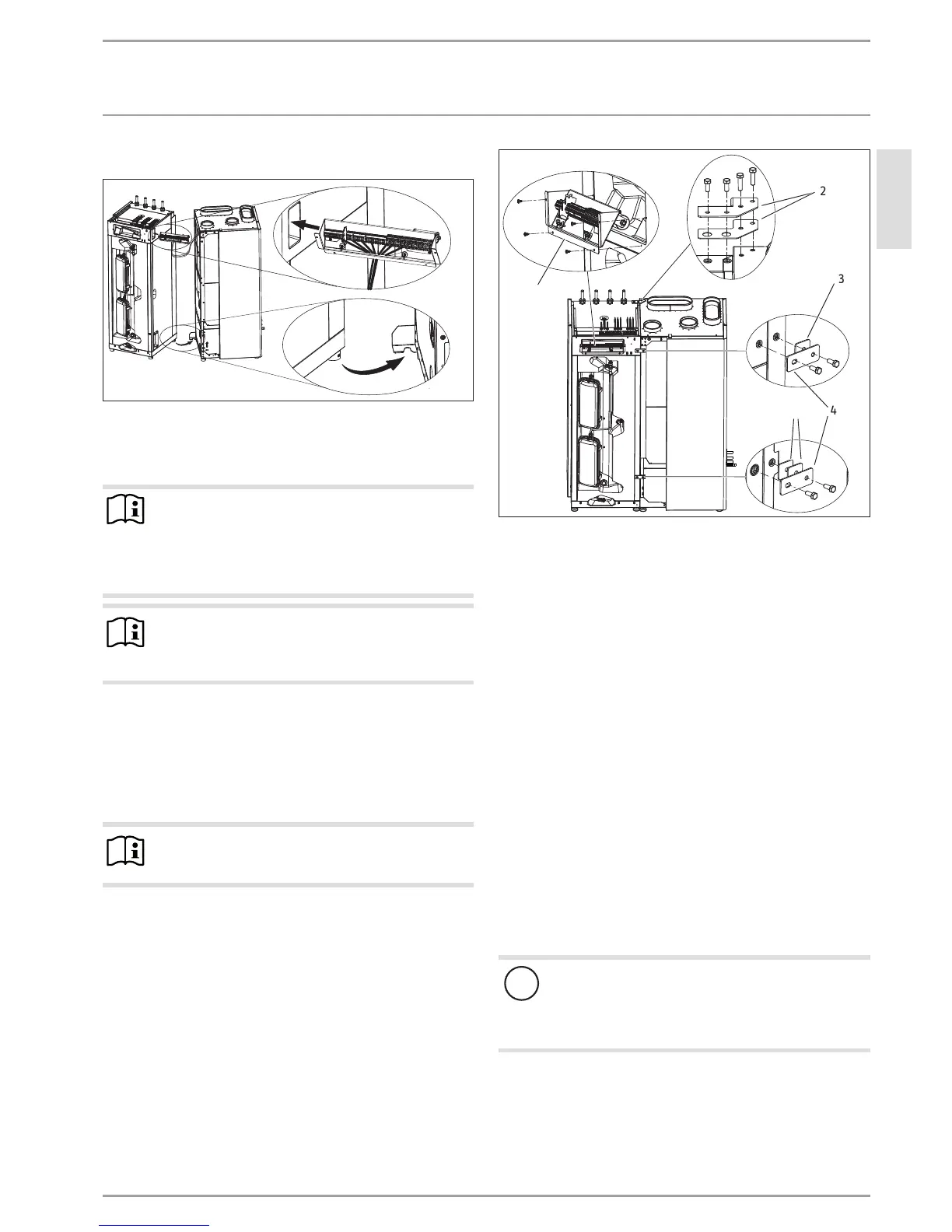
Inserting the terminal bracket into the cylinder module
26_04_01_0551
Push the terminal bracket through the aperture located at the
top r.h. side of the cylinder module.
Pushing the cylinder and the function modules together
Note
An air hose to capture the differential pressure runs
along the l.h. side of the function module. This air hose
must run inside the curved groove cut into the thermal
insulation.
Ensure that this air hose is seated correctly.
Note
The adjustable feet must not be fully screwed in, oth-
erwise you will not be able to push the joining bracket
between the bottom panel and the foot.
Push the cylinder module further towards the function mod-
ule, so that the rear r.h. adjustable foot of the cylinder mod-
ule is pushed into the recess in the joining bracket.
The lower joining bracket ensures that the cylinder module
is automatically pushed into its final position. Level the cyl-
inder module and the function module vertically to the same
height by turning the adjustable feet.
Note
The cylinder module drops 4 to 5mm when its cylinder
is filled.
Turning anti-clockwise exposes more of the adjustable feet, mean-
ing the appliance moves upwards. The cylinder module must be
snug against the function module.
26_04_01_0560
1
2
4
3
3
1 Terminal bracket
2 Joining plates
3 Spacer
4 Horizontal locking bracket
Guide the terminal bracket forwards out of the cylinder
module.
Offer the terminal bracket up to the front of the cylinder
module frame. Ensure that the cables are positioned so that
the are free of stress/pressure.
Attach the terminal bracket to the cylinder module using four
screws.
Connection top back
Connect the function module and the cylinder module at
the top back by positioning joining plates and inserting two
screws each through the joining plate into the function mod-
ule and the cylinder module.
Fitting the horizontal locking bracket to the front
Connect the function module and cylinder module at the
front by securing one horizontal locking bracket each at the
top and bottom using screws. The spacers supplied enable
you to align the cylinder and function modules. Position a
spacer on the side of the function module, behind the upper
cross bolt and two spacers behind the lower cross bolt.
!
Material losses
Before filling, tighten the screws only lightly so that the
paint finish is not damaged when the cylinder module
moves down during filling. Tighten the screws after fill-
ing.
 Loading...


