6 | LWZ304-404 SOL www.stiebel-eltron.com
INSTALLATION
Appliance description
3.4.2 Cooling
The refrigeration unit of the heat pump may be reversed. In cool-
ing mode, heat may be extracted from the heating circuit and
transferred to the outdoor air.
Cooling always requires a separation of the volume flow of heat-
ing circuits and appliance. Therefore a low loss header or buffer
cylinder must be installed in this case.
A low loss header can only be used if the fan convectors in the
cooling system are large enough. In the case of area cooling, a
buffer cylinder must be installed.
The "COOLING" menu will only be activated when connecting
an external programming unit. The menu is only visible on the
external programming unit. During commissioning, the exter-
nal programming unit must be assigned to the heating circuit.
Active cooling is impossible without an external programming
unit. Only the programming units with selected terminal address
1 or 2 transmit temperature and humidity values to the appliance
controller.
When activating cooling mode, assign the type of heat transfer to
the heating circuits that will be active during cooling.
- Area cooling means: underfloor heating systems, wall heat-
ing systems and generally all heating systems that have no
means of draining any condensate. The set flow temperature
of at least 18°C will only be enabled if the relative humidity
in the room permits this. Otherwise the flow temperature
will be limited. An operative programming unit with terminal
address 1 or 2 must be provided for every heating circuit
with area cooling, otherwise that circuit will be disabled.
- Fan convector means: Fan convectors or other heating/cool-
ing elements that have a facility for collecting condensate
and draining it to a specific place. Thermally insulate heating
pipes with vapour diffusion-proof material. The flow temper-
ature must be at least 7°C.
!
Material losses
If for area heating systems radiators or convectors without
condensate drain setting "FAN CONVECTORS" is selected
in the "COOLING SYSTEM" menu, there would be a risk of
severe moisture-related damage through condensation.
Conventional thermostatic valves are closed when cooling is re-
quired. Cooling will be possible when the thermostatic or zone
valves are set to cooling, provided they offer such a function.
Alternatively, these valves may also be opened via the cooling
signal (output KUE on terminal X4). Temporarily, valves may also
be opened fully for cooling.
Cooling is not possible in manual mode.
Cooling function
Parameter "COOLING MODE" must be set to "ON". Cooling is ena-
bled when the appliance is in summer mode and the outside tem-
perature exceeds the set room temperature for heating (parameter
"ROOM TEMPERATURE DAY" in menu "HEATING/ ROOM TEMPER-
ATURES HC1" or "ROOM TEMPERATURES HC2") for 2hours by 3K.
If the room temperature is then higher by the value set under
"HYST. ROOM TEMP." than the set room temperature for cooling
(parameter "ROOM TEMPERATURE DAY" in menu "SETTINGS/
COOLING/ ROOM TEMPERATURES HC1" or "ROOM TEMPERATURES
HC2"), then the system prepares for cooling. The display shows
a snowflake. The circulation pump starts, the three-way valve
changes over to the heating circuit and the "cooling" output is
activated in order to, for example, open the thermostatic valves
in the rooms to be cooled.
The compressor starts if the flow temperature lies higher than the
set flow temperature for cooling by the amount of flow tempera-
ture hysteresis. The compressor stops when it is lower than this
by the amount of flow temperature hysteresis.
The dew point is monitored in area heating systems. The dew
point is that temperature at which humidity in the air begins to
condensate. The compressor stops once the flow temperature is
within 2 K of the dew point. The compressor will be enabled if
it lies above this value by the hysteresis set in parameter "HYST.
FLO W T EMP.".
3.4.3 Frost protection for the cross-countercurrent heat
exchanger
A heat exchanger in the path of the outdoor air flow preheats
the outdoor air, and thus prevents the cross-countercurrent heat
exchanger from freezing up.
3.4.4 Buffer mode for air heating
If a heating system with a low draw-off rate and little thermal
capacity is used, e.g. air heating coil through which the domestic
ventilation flow is routed, the lower section of the DHW cylinder
can be utilised as a buffer cylinder.
Excess heat can be temporarily stored there, thereby reducing
compressor cycling. This function can be activated in the "DHW"
menu using the "DHW BUFFER MODE" (P84) parameter.
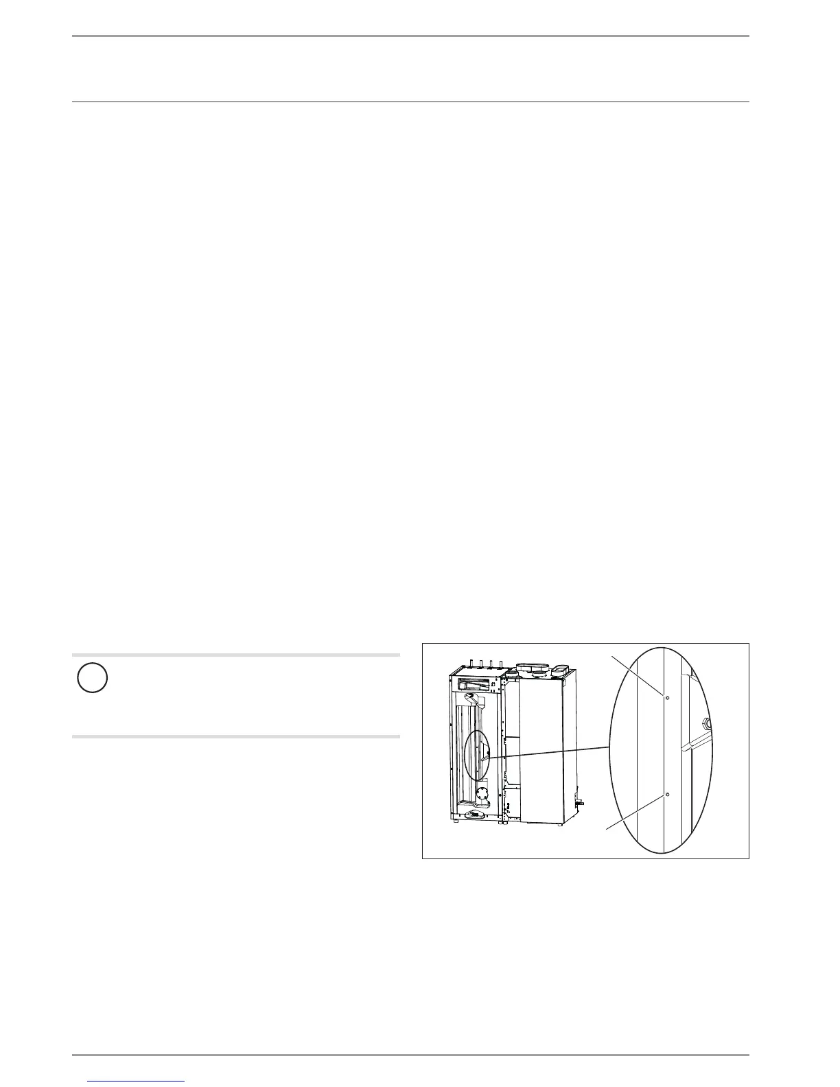
You can determine the operating mode by positioning the cylinder
temperature sensor.
1
2
D0000039615
1 Cylinder temperature sensor - upper position
2 Cylinder temperature sensor - lower position
If the cylinder temperature sensor is in the upper position, ap-
prox. 100l water are always maintained at the required DHW
temperature. The remaining cylinder capacity is used as a heating
buffer and have a temperature corresponding to the heating flow
temperature.
If the cylinder temperature sensor is in the lower position, the
entire cylinder content is always maintained at the required DHW
temperature.
 Loading...


