24 |WPF | WPF cool www.stiebel-eltron.com
INSTALLATION
Preparations
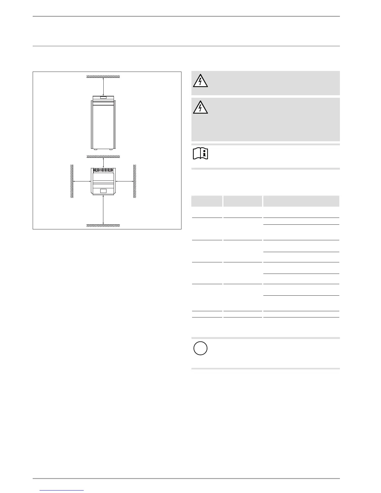
10.4.1 Minimum clearances
≥500
≥50
≥500
≥500
≥1000
D0000034469
Maintain the minimum clearances to ensure trouble-free op-
eration of the appliance and facilitate maintenance work.
10.1 Electrical installation
DANGER Electrocution
Carry out all electrical connection and installation work
in accordance with national and regional regulations.
DANGER Electrocution
Only use a permanent connection to the power supply.
Ensure that the appliance can be separated from the
power supply by an isolator that disconnects all poles
with at least 3mm contact separation. This requirement
can be met with contactors, circuit breakers, fuses, etc.
Note
The specified voltage must match the mains voltage. Ob-
serve the type plate.
Install cables with the following cross-sections in accordance with
the respective fuse rating:
Fuse/MCB
rating
Assignment Cable cross-section
C 16 A Compressor
(three phase)
2.5 mm²
B 16 A
Electric emergency/
booster heater (BH)
(three phase)
2.5 mm²
1.5 mm² with only two live cores and
routing on a wall or in an electrical con-
duit on a wall.
C 16 A
Compressor
WPF 05 S / 07 S
(single phase)
1.5 mm² for open routing. Note the type
of routing!
2.5 mm² for routing through a
wall. Note the type of routing!
C 25 A
Compressor
WPF 10 S / 13 S
(single phase)
4.0 mm² for open routing. Note the type
of routing!
6.0 mm² for routing through a
wall. Note the type of routing!
B 16 A
Electric emergency/
booster heater (BH)
(single phase)
2.5 mm² for routing through a
wall. Note the type of routing!
1.5 mm² when routing a multi core line
on a wall or in an electrical conduit on
a wall.
B 16 A Control unit 1.5 mm²
The electrical data is provided in the chapter "Specification / Data
table".
!
Material losses
Provide separate fuses/MCBs for the two power circuits
of the compressor and the electricemergency/booster
heater.
 Loading...