OPERATION
Menu structure
12 |WPF | WPF cool www.stiebel-eltron.com
5.2 DIAGNOSIS menu
For heating system and heat pump troubleshooting and analysis,
all important process data and bus subscribers can be queried
under DIAGNOSIS and a relay test can be carried out.
Note
The menu item RELAY TEST SYSTEM is protected by a
code and can only be accessed by a qualified contractor.
Level 2 Level 3
SYSTEM STATUS BUFFER CHARGING PUMP
DHW VALVE
HTG CIRC PUMP
MIXER PUMP
MIXER OPEN
MIXER CLOSED
SOURCE PUMP
COOLING MODE
POWER BLOCKED
HEAT PUMP STATUS REM IDLE TIME in minutes
COMPRESSOR
NHZ 1
NHZ 2
SYSTEM BUS SUBSCRIBER
HEAT PUMP TYPE
INTERNAL CALCULATION INTERVAL
LIVE STAGES
FAULT LIST see fault table
RELAY TEST SYSTEM BUFFER CHARGING PUMP
DHW VALVE
HTG CIRC PUMP
MIXER PUMP
MIXER OPEN
MIXER CLOSED
NHZ 1
NHZ 2
NHZ 3
SOURCE PUMP
COOLING MODE
DRAIN HYD MFG
5.2.1 Fault list
In the fault list, you receive an overview of the faults most recently
registered by the appliance. The fault list contains up to 20 fault
messages. The display, however, can show only 2. Turn the scroll
wheel to access the other entries in the fault list.
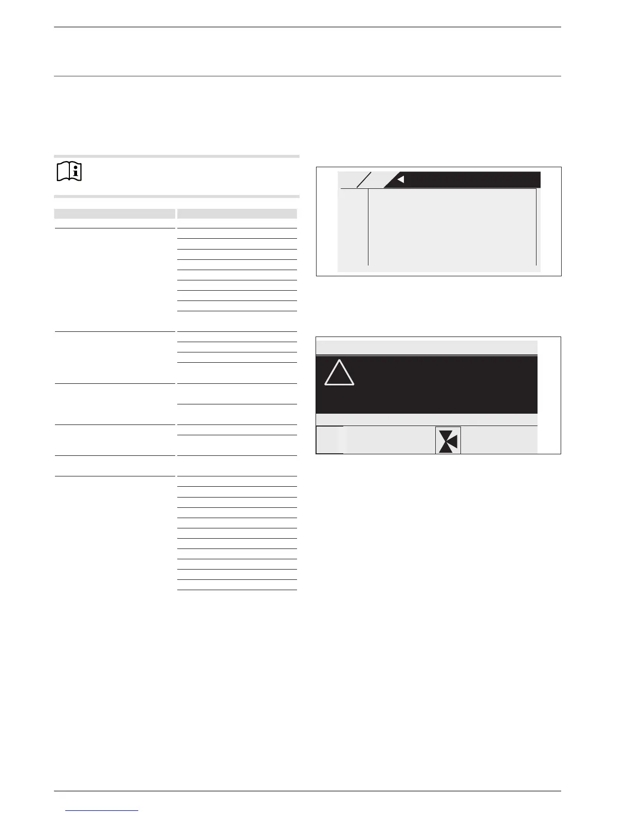
MAIN DIAG
FAULT LIST 1/1
01. SENSOR BREAK E 71
10:26 14.JUN 13
02. MIN SRCE TEMP
17:45 25.JUN 13
5.2.2 Fault message
If the appliance registers a fault, this is clearly displayed with the
message shown below.
COMFORT MODE
!
FAULT
SENSOR BREAK E 71
TUESDAY 14.JUN 13 16:27 TIME
If more than one fault occurs, the most recent one is shown con-
tinuously. Please inform your contractor.
5.2.3 Relay test
You can control all relay outputs of the controller from here.
 Loading...