www.stiebel-eltron.com WPF | WPF cool | 43
INSTALLATION
Troubleshooting
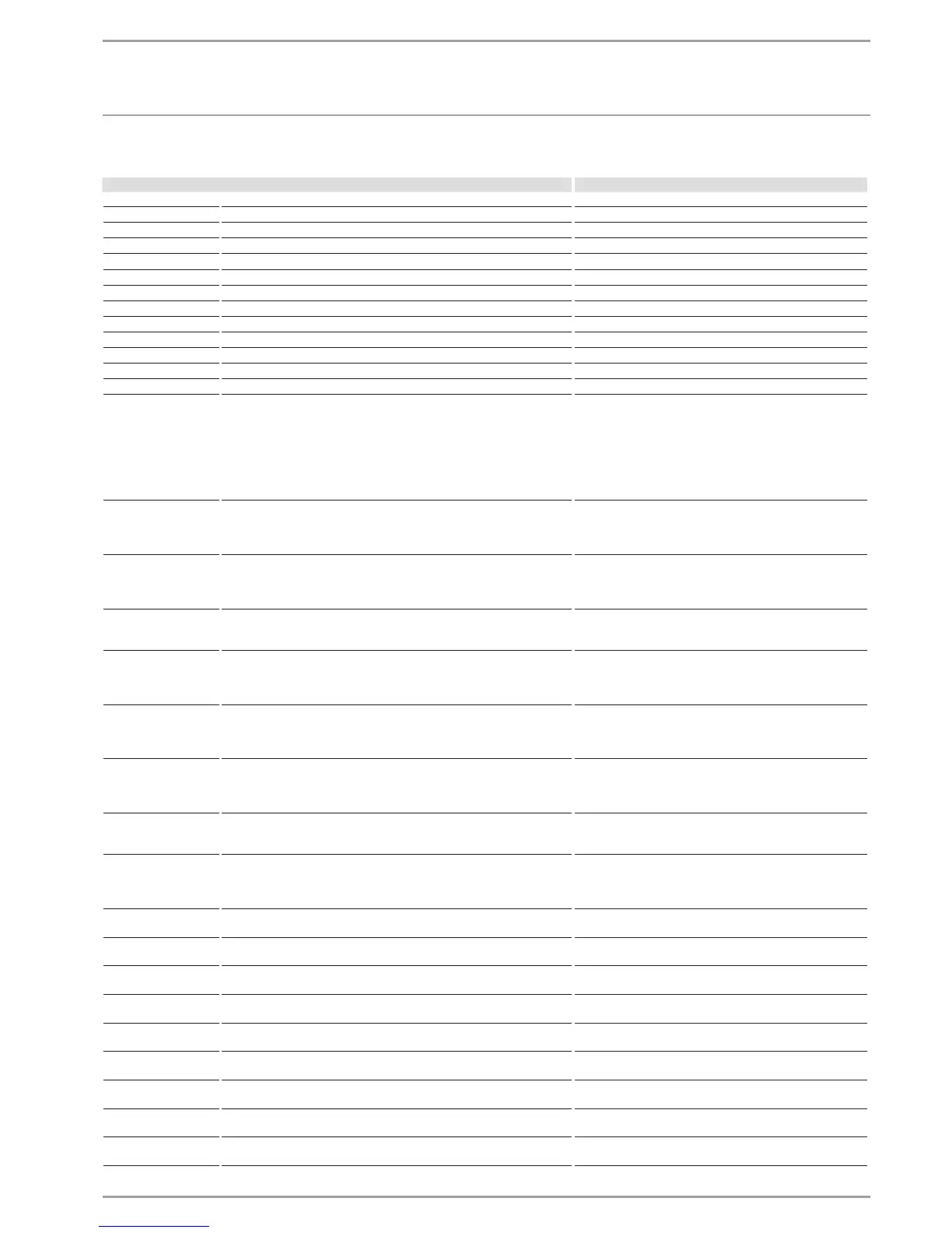
16.5 Fault table
Fault display Cause Remedy
SENSOR BREAK E 70 The mixer sensor is faulty. Check the sensor terminal on the MFG or replace sensor.
SENSOR BREAK E 71 The source sensor is faulty. Check the sensor terminal on the MFG or replace sensor.
SENSOR BREAK E 72 The flow sensor is faulty. Check the sensor terminal on the MFG or replace sensor.
SENSOR BREAK E 73 The return sensor is faulty. Check the sensor terminal on the MFG or replace sensor.
SENSOR BREAK E 75 The external sensor is faulty. Check the sensor terminal on the MFG or replace sensor.
SENSOR BREAK E 76 The DHW sensor is faulty. Check the sensor terminal on the MFG or replace sensor.
SENSOR BREAK E 80 The remote control is faulty. Check the sensor terminal on the MFG or replace sensor.
SENSOR BREAK E 130 The HP sensor is faulty. Check the sensor terminal on the MFG or replace sensor.
SENSOR BREAK E 128 The LP sensor is faulty. Check the sensor terminal on the MFG or replace sensor.
ERR T FLO BH MFG The flow sensor of the electric emergency/booster heater is faulty. Check the sensor terminal in the MFG or replace sensor.
ERR T FLO HP MFG The heat pump flow sensor on the MFG is faulty. Check the sensor terminal on the MFG or replace sensor.
ERR T RTRN MFG The return sensor on the MFG is faulty. Check the sensor terminal on the MFG or replace sensor.
ERR T DHW MFG The DHW sensor on the MFG is faulty. Check the sensor terminal on the MFG or replace sensor.
HP SENSOR MAX
Fatal error in heating mode only, 5 faults in 5 minutes compressor runtime
The fault will be written to the fault list and the system will be perma-
nently shut down after the system has been shut down 5 times within the
operating time (5 minutes). Generally, the shutdown via HP sensor max is
a controlled shutdown that is only displayed for information and for the
duration of the idle time, i.e. it is not entered into the fault list. Only fre-
quent shutdowns over a short period of time point towards a fault and are
therefore entered into the fault list.
Only when a fault has been entered into the fault list: Check
flow temperature monitoring and HP sensor. Check flow rate
and temperature of heating side.
MAX HOT GAS T
The compressor will be stopped for the minimum idle time if a hot gas
temperature of 130 °C is exceeded. This is a normal controlled shutdown
that is not entered into the fault list. The reason for the shutdown is dis-
played for information during the idle time.
This requires no action, as it is a controlled shutdown.
HIGH PRESSURE
After the compressor has started, and after a delay of 15 seconds, mask-
ing checks whether the relay K9 is open. A HP limit switch has responded,
if that is the case. The fault is written to the fault list, and the system is
permanently shut down.
Monitor the flow temperature and check the HP sensor.
Check the flow rate and the temperature on the heating side.
LOW PRESSURE
The system will be permanently shut down after the fault has occurred
five times within the operating time (idle time x 50 plus 20 minutes). The
fault will be written to the fault list after it has occurred for the first time.
Check the flow rate and the layout of the source side.
Check the refrigerant level.
MIN SRCE TEMP
Minimum source temperature
The defined minimum source temperature was not reached.
The fault is written to the fault list. The compressor starts again after the
selected idle time has expired.
Check the minimum source temperature and change it if re-
quired. Check the source flow rate: Check source design.
CONTACTOR STUCK
Each time the compressor is switched off, the system checks after 10 sec-
onds whether the relay K9 is open. A contactor is stuck, if that is the case.
The fault is written to the fault list, and the system is permanently shut
down.
Check contactors K1 and K2 and replace if required.
NO OUTPUT
After the compressor has started, the pressure must have risen by 2 bar
within 10 seconds. A fault has occurred, if that is not the case, and the
fault will be written into the fault list, if that is its first occurrence, and the
system is permanently shut down.
Compressor turns in the wrong rotational direction. Change
the rotational direction by interchanging two supply cores.
POWER-OFF
The power supply utility has blocked the heat pump (see chapter „Installa-
tion/ Troubleshooting/ Fault message/ The heat pump is not running“).
No action required. If this message is still shown despite en-
abling by the power supply utility, the brine pressure switch
has responded (see „CHECK BRINE PRESSURE“).
CHECK BRINE PRESSURE
The pressure in the brine line is too low. If this is the case, there is a leak
in the brine line or the heat pump has been charged with inadequate
brine.
Check the brine line for leaks and remedy any that are found.
Subsequently recharge the system (see chapter „Installation/
Installation/ Installing the heat source system/ Connection
and brine charging/ Charging the brine circuit“).
TO T FLO BH MFG The flow sensor of the electric emergency/booster heater is faulty. Check the communication cable terminal or replace the com-
munication cable.
TO T FLO HP MFG The heat pump flow sensor on the MFG is faulty. Check the communication cable terminal or replace the com-
munication cable.
TO T RET MFG The return sensor on the MFG is faulty. Check the communication cable terminal or replace the com-
munication cable.
TO T DHW MFG The DHW sensor on the MFG is faulty. Check the communication cable terminal or replace the com-
munication cable.
TO FL RATE HC MFG Faulty communication with the MFG. Check the communication cable terminal or replace the com-
munication cable.
TO PRES HC MFG Faulty communication with the MFG. Check the communication cable terminal or replace the com-
munication cable.
TO P SOL MFG Faulty communication with the MFG. Check the communication cable terminal or replace the com-
munication cable.
TO PUMP HC MFG Faulty communication between heating circuit pump and MFG. Check the communication cable terminal or replace the com-
munication cable.
TO P BRINE MFG Faulty communication between brine circuit pump and MFG. Check the communication cable terminal or replace the com-
munication cable.
 Loading...