STIHL 064, 066 69
9.5 Generato
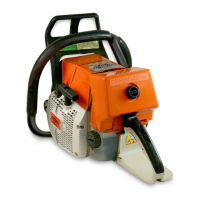
Top and center:
Front handle mounting screws
Bottom: 1 = Insulating tube
Wires threaded through grommet Wires correctly positioned in rear 2 = Male connector
in carburetor box handle recess 3 = Female connector
- Take out the four screws and - Remove the air filter - see 11.1.
remove the front handle.
- Remove the shroud - see 3.2.
Important: The special screws
used for polymer joints are se- - Remove the flywheel - see 5.1.5.
cured with Loctite. Always heat the
screwed joint before loosening, - Remove the ignition module
e.g. with a hair dryer. Take care - see 5.1.6.2.
not to overheat the polymer.
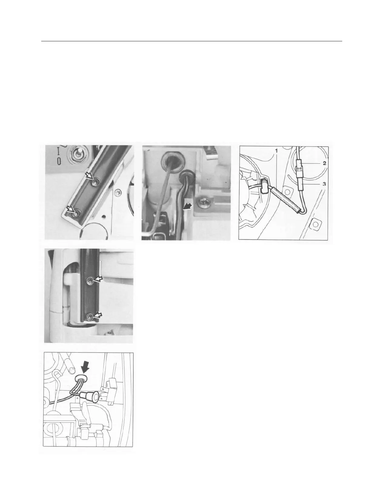
- On 066, pull the male connector
- Pull both wires through the grom- out of the female connector.
met and out of the carburetor box.
- Use a small screwdriver to press
Reverse the above sequence to fit down the anchor hook of the ter-
the new front handle. urinal pin and then pull off the pin
housing.
Note: Secure the handle mounting
screws with Loctite - see 12.2. - Pull the insulating tube off the
connecting wire.
Check that wire 2 of the front
handle heating element and the Note: Removal of the generator
generator wire 1 are properly is the same as for the 064. The
positioned in the rear handle. disconnection of the electrical
wires, as described below, is only
necessary on the 064.
- Take the switch shaft out of its
ivot mounts - see 8.3.
 Loading...