FR 130 T
English
15
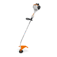
N Place the clamp (3) in the loop
handle (4) and position them both
against the drive tube (5).
N Position the clamp (6) against the
drive tube.
N Place the barrier bar (2) in position
as shown.
N Line up the holes.
N Insert the screws (7) in the holes
and screw them into the barrier bar
as far as stop.
N Go to "Securing the Loop Handle".
Leave the barrier bar permanently
mounted to the loop handle.
Mounting the Loop Handle without
Barrier Bar
N Place the clamp (3) in the loop
handle (4) and position them both
against the drive tube (5).
N Position the clamp (6) against the
drive tube.
N Line up the holes.
N Fit the washers (8) on the
screws (7), and insert the screws in
the holes.
N Screw the square nuts (1) onto the
screws (7) as far as stop.
N Go to "Securing the Loop Handle".
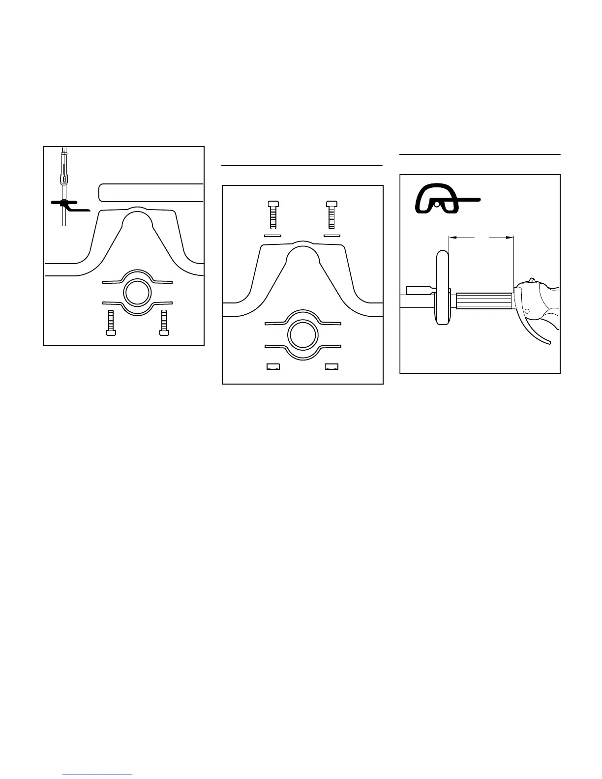
Securing the Loop Handle
N Secure the loop handle (4)
about 20 cm/8 in (A) forward of the
control handle (9).
N Line up the loop handle.
N Tighten down the screws firmly –
lock the nuts if necessary.
The sleeve (10) (not fitted on all models)
must be between the loop handle and
the control handle.

 Loading...