FR 130 T
English
19
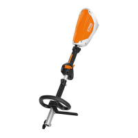
N Screw the mowing head
counterclockwise on to the shaft (1)
as far as stop.
N Block the shaft.
N Tighten down the mowing head
firmly.
NOTICE
Remove the tool used to block the shaft.
Removing the Mowing Head
N Block the shaft.
N Unscrew the mowing head
clockwise.
Mounting Metal Cutting Attachment
Keep the leaflet and packaging of the
metal cutting attachment in a safe place.
WARNING
Wear protective gloves to reduce the
risk of direct contact with the sharp
cutting edges.
Mount only one metal cutting
attachment.
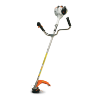
Check direction of rotation of cutting
attachment
Cutting attachments with 2, 3 or 4 teeth
(1, 4, 5) may point in either direction –
these cutting attachments must be
turned over regularly to help avoid one-
sided wear.
The cutting edges of the grass cutting
blades (2, 3) must point clockwise.
WARNING
Direction of rotation is indicated by an
arrow on the inside of the deflector.
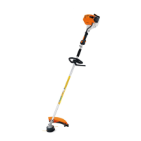
N Place the cutting attachment (6) on
the thrust plate (7).
WARNING
Collar (see arrow) must engage the
cutting attachment's mounting hole.
Securing the cutting attachment
N Fit the thrust washer (8) – convex
side must face up.
N Fit the rider plate (9).
N Block the shaft (10).
N Use the combination wrench (12) to
screw the mounting nut (11) on to
the output shaft counterclockwise
and tighten it down firmly.
WARNING
If the mounting nut has become too
loose, fit a new one.

 Loading...