- Inspect rubber buffers, replace if
necessary.
- Adjust gap after fitting the AV
housing and support.
Assemble all parts in the
reverse sequence.
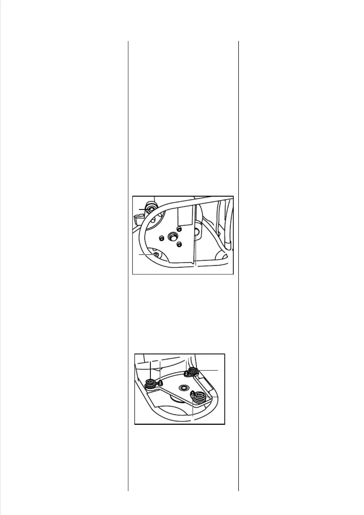
The anti-vibration connection
between the engine and support
frame consists of three springs.
- Remove flexible shaft from
clutch housing - see 10.5.
•
Take spline screws (1) and hex.
head screw (2) out of clutch hou-
sing.
- Take powerhead off the support
plate.
•
Hold screws steady and unscrew
the nuts (1).
•
Remove the springs (2) from the
support plate.
Reassemble in the reverse
sequence.
- Use new locknuts and tighten
them down to 10 Nm (7.5 lbf.ft).
- Tighten down spline screws and
hexagon head screw to 10 Nm
(7.5 lbf.ft).
9.3 Repair
(FR 350/450)
2
5
0
R
A
1
6
2
1
1
2
V
A
2
5
0
R
A
2
4
2
2 1 1
2
1
2
V
A
50 FS 120, 200, 300, 350, 400, 450, FR 350, 450

 Loading...