Passenger Stairway PS-813B/E Boeing | 11
SECTION 1 - PROCEDURES, SPECS & CAPABILITIES
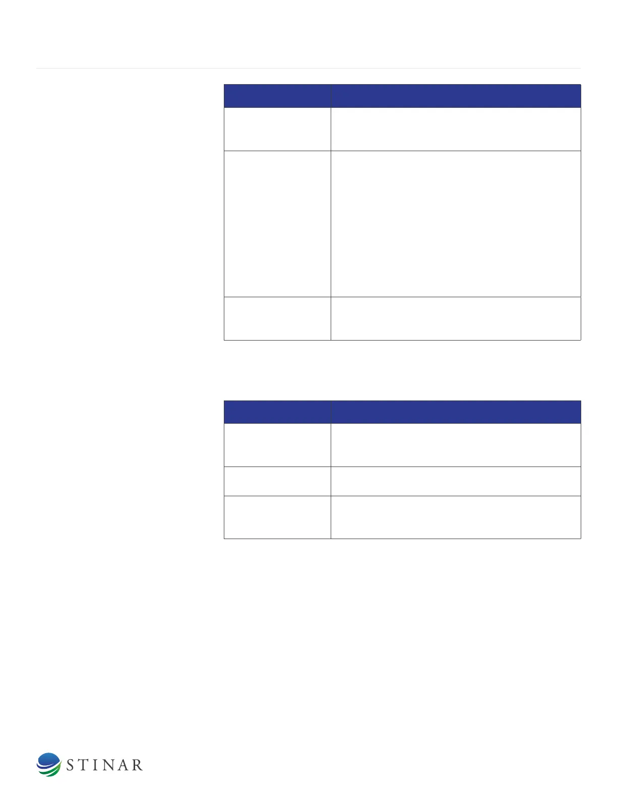
COMPONENT DESCRIPTION
Check Valve
The check valve is included in the hydraulic pump
line to prevent hydraulic pressure from backing up
against the main pump when the hand pump is used.
Directional Control
Valve (see Figure
1.1.3.1)
The directional control valve is a three-spool valve
incorporating an adjustable pressure relief valve.
One valve spool directs oil to and from the A-frame
cylinders. Another controls the stairway cylinder. The
third spool controls the four stabilizer cylinders. Each
spool is manually-operated by a control handle.
The control valve is considered “power beyond”. If
equipped, excess oil from the control valve ows to
the control valve which controls the ow of hydraulic
oil of the hydraulic motor powering the drive wheel.
Pressure Relief Valve
The system relief valve is part of the directional
valve. It can be adjusted manually by turning an
adjustment screw.
1.1.3.2 | Hydraulic Cylinders
This unit has seven hydraulic cylinders for raising and lowering the
stairway, A-frame and stabilizers.
COMPONENT DESCRIPTION
Stairway Cylinder
The stairway cylinder is located beneath the
stairway. A lock valve and a ow control valve are
located near the inlet/outlet port of this cylinder.
A-frame Cylinders
The A-frame contains two cylinders. A lock valve and
a ow control are provided for these two cylinders.
Stabilizer Cylinders
Four stabilizer cylinders are located near the corners
of the stairway chassis. There is one lock valve on
each cylinder.
1.1.3.3 | Lock Valves
There are six lock valves in the system (see Hydraulic Cylinders above).
The lock valves trap uid under pressure when the pump is shut o,
locking the cylinders in position.
1.1.3.4 | Flow Control Valves
Flow control valves on the A-frame and stairway cylinders regulate the
lowering speed of the A-frame and stairway.
1.1.3.5 | Return Line Filter
The return line lter puries hydraulic oil returning to the tank. This lter