Passenger Stairway PS-813B/E Boeing | 8
SECTION 1 - PROCEDURES, SPECS & CAPABILITIES
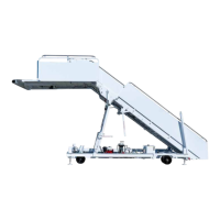
The Stinar Model PS-813B/E Passenger Stairway (see Figure 1.1) is a towable
passenger boarding stairway. Height adjustment is made by means of a
telescoping A-frame mechanism and the upper stairs telescoping into the
lower stairs. The stairway incorporates an aircraft boarding platform at
the top of the stairs. The platform provides access to aircraft cabins with
doorsill heights ranging from 96 in. (2440 mm) to 228 in. (5790 mm) above
ground level. Four hydraulically-operated stabilizers provide stability when
the stairway is raised.
A gasoline engine on the chassis is coupled to a hydraulic pump that
operates whenever the engine is running. The pump provides hydraulic
power to raise and lower the stairway, A-frame and stabilizers. A
hand pump provides emergency power in case of main power failure.
Mechanical ratchets lock the stairway and A-frame in position. A 12 VDC
electrical system provides power for illuminating the stairs and for the
engine electric starter.
1.1.1 | Chassis
The stairway chassis is a steel channel frame to which the stairway sub-
assemblies are attached. The chassis is tted with spring-loaded dual-
wheel casters at the stairs end and with a rigid axle beneath the A-frame.
The axle is tted with hubs having automotive-type bearings. The wheels
have ve bolts and 8 in. rims and are tted with 4:00 x 8 solid tires.
Mounting brackets for the stairway and A-frame are provided at opposite
ends of the chassis. A stabilizer is attached to each corner of the frame.
The frame provides mounting brackets for the electrical system and the
hydraulic system and for the engine.
A tow bar is attached to the stairway/chassis for towing purposes. When
not in use, the tow bar should be lifted and latched to the chassis.
1.1.2 | Stairway, Platform and A-frame
The elevating stairway consists of two stair sections supported by a
telescoping A-frame. The lower stairs assembly is attached to the chassis
by a shaft, which enables the stairs to pivot. The top of the lower stairway
is connected to the chassis by the A-frame assembly. The A-frame
permits the angle of inclination (and thus the platform height) of the
stairway to be adjusted. The upper stairs section, which includes the
platform, can be extended and retracted.
1.1.2.1 | A-frame
The A-frame assembly (see Figure 1.1.2.1) supports the stairs sections and
can be raised or lowered to adjust the angle of the stairway and platform.
The A-frame consists of two sections.
1. The inner A-frame is the lower of the two sections. The base of the
inner A-frame is secured by pivot pins to a support bracket welded
to the chassis.
1.1 DESCRIPTION
SECTION 1 - PROCEDURES, SPECS & CAPABILITIES