Passenger Stairway PS-813B/E Boeing | 5
4.2.2 | How to Order Parts and Assemblies . . . . . . . . . . . . . . . . . . . . 36
PARTS ORDER FORM � � � � � � � � � � � � � � � � � � � � � � � � � � 37
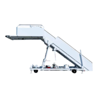
Fig 1.1 | Passenger Stairway, Model PS-813B/E 38
Fig 1.1.2.1 | A-frame 39
Fig 1.1.3 | Hydraulic Schematic 40
Fig 1.1.3.1 | Primary Control Station 41
Fig 1.1.4 | Electrical Schematic 42
Figure 1.2.1.2 | Primary Control Station 43
Figure 2.1.7.1 | Lubrication Points 44
Figure 2.1.7.2 | Lubrication Points 45
Figure 2.1.7.3 | Lubrication Points 46
Figure 2.2.1.1 | Hydraulic Schematic 47
Figure 2.2.1.2 | Electrical Schematic 48
Figure 2.3.1 | Primary Control Valve 49
Figure 2.3.3 | Adjustment Bolts 50
Figure 4.3.1 | Passenger Stairway, Model PS-813B/E 51
Figure 4.3.1 | Passenger Stairway, Model PS-813B/E - Table 52
Figure 4.3.1 | Passenger Stairway, Model PS-813B/E - Table Pt.2 53
Figure 4.3.2 | Stairway Chassis Assembly 54
Figure 4.3.2 | Stairway Chassis Assembly - Table 55
Figure 4.3.3 | Upper Stairs and Platform 56
Figure 4.3.3 | Upper Stairs and Platform - Table 57
Figure 4.3.4 | Lower Stairs Assembly 58
Figure 4.3.4 | Lower Stairs Assembly - Table 59
Figure 4.3.5 | Stairway Ratchet Assembly 60
Figure 4.3.5 | Stairway Ratchet Assembly - Table 61
Figure 4.3.6 | A-frame Assembly 62
Figure 4.3.6 | A-frame Assembly - Table 63
Figure 4.3.7 | Hydraulic System 64
Figure 4.3.7 | Hydraulic System - Table 65
Figure 4.3.8 | Stairway Extend Cylinder 66
Figure 4.3.9 | Electrical Schematic 67
Figure 4.3.9 | Electrical Schematic - Table 68
Figure 4.3.10 | Control Station 69
Figure 4.3.10 | Control Station - Table 70