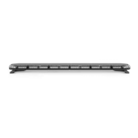
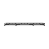
The K-FORCE® 55 is a full light bar designed for emergency vehicle warning applications. It is manufactured by SpeedTech Lights, Inc. and is available in two models: F-TKF55 and F-LKF55.
Function Description:
The K-FORCE® 55 full light bar is intended to alert pedestrians and other operators to the presence of personnel, emergency vehicles, emergency sites, and other warning needs. It features various lighting functions including full 360° warning lights, forward-facing lights, rear-facing lights, take-down lights, alley lights, cruise lights, and traffic advisor functions (left arrow, center out arrow, right arrow). The light bar is controlled via a Supreme Control Switch Box (sold separately) or by direct wiring. It incorporates non-volatile memory to recall the last selected flash pattern.
Important Technical Specifications:
- Voltage: 12 VDC
- Amps: < 18.2
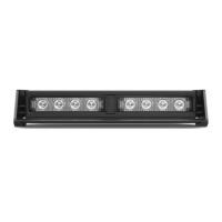
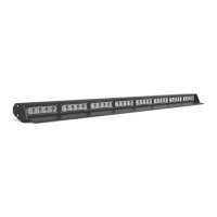
- Optic: TIR / Linear
- LED Count: TIR: 104 / Linear: 156
- Cable Length: 12' Light Bar Cable, 12.5' Cig Plug Cable, 12.5' AUX Cable
- Flash Patterns: 33 distinct flash patterns
- Dimensions: Approximately 55.1" (length) x 11.4" (width) x 3.6" (height)
Wiring Diagram Overview:
The light bar utilizes a multi-wire harness for various functions:
- Main Power: Red (Thick) for Positive, Black (Thick) for Negative.
- Warning Functions:
- Brown: Forward Facing Lights
- Light Blue: Rear Facing Lights
- Purple: Full 360° Warning Lights
- Yellow: Flash Pattern (cycles through patterns)
- Auxiliary Lights:
- Light Green: Take Down
- Green: Alley
- Traffic Advisor:
- Blue: Left Arrow
- White: Center Out Arrow
- Orange: Right Arrow
- Special Functions:
- Grey: Cruise Lights (4 Corners)
- Control Box Connections (Thin Wires):
- Red (Thin): Control Box In Positive
- Black (Thin): Control Box In Negative
- Pink (Thin): Control Box Out Positive
- Yellow/Green (Thin): Control Box Out Negative
- Note: All cables except Negative contact +12 VDC.
- AUX Wiring Diagram:
- Red: AUX Positive
- Blue: AUX Negative
Usage Features:
The K-FORCE® 55 can be operated with a Supreme Control Switch Box (sold separately).
- Slide Switch:
- Off: Turns off all warning functions.
- 1st position: Powers front of the bar and forward-facing 45° warning modules.
- 2nd position: Powers back of the bar and rear-facing 45° warning modules.
- 3rd position: Powers all warning functions.
- Take Down Button:
- 1st press: Take Down Steady Burn On.
- 2nd press: Take Down Off.
- Alley Button:
- 1st press: Alley Steady Burn On.
- 2nd press: Alley Off.
- Traffic Advisor Buttons:
- Traffic Advisor LEDs flash in sequence with warning mode when not activated.
- Left Arrow: Right to Left Traffic Sweep.
- Center Out Arrow: Center Out Traffic Sweep.
- Right Arrow: Left to Right Traffic Sweep.
- Flash Pattern Button:
- Cycles to the next flash pattern with each press.
- Non-volatile memory recalls the last flash pattern selected.
- Hold for 2 seconds to toggle Steady Burn mode.
- Hold for 3 seconds to toggle Random pattern mode.
- Cruise Button (45° (Four Corner) Modules):
- 1st press: Cruise Steady Burn On.
- 2nd press: Cruise Off.
- AUX Button:
- Toggle power to AUX cables On and Off.
- Flash Pattern List (33 patterns): Includes Steady Burn, various alternating flashes (Triple, Double, Single), Center Out, Quad Flash, Rapid Pulse, Stacking, Clockwise/Counter Clockwise Rotations, and Accelerating Flash Alternating.
- Flash Pattern Shortcuts: Hold Flash Pattern button for 2 seconds for Steady Burn, 3 seconds for Random pattern.
- Extension Cable (Sold Separately): Allows for extended reach between the light bar and the control box. Installation involves connecting corresponding ends or cutting and soldering wires for specific cable types.
Mounting Options (Sold Separately unless otherwise noted):
- Foot Brackets (Included): Adjustable along the aluminum track for flat, even contact with the roof.
- Universal Mounting Brackets (Included): Attach to Foot Brackets via I-bolt, then secure to vehicle via pre-drilled holes and user-supplied screws.
- Vehicle Specific Mounting Brackets: Similar to universal brackets, but designed for specific vehicle models. Attach to Foot Brackets via I-bolt, then secure to vehicle via pre-drilled holes and user-supplied screws.
- Stud Mount: Replaces Foot Bracket. Main mounting bolt goes through the Stud Mount, which then attaches to the light bar using existing screws.
- Headache Rack Mount: Replaces Foot Brackets. Attaches to the light bar using two vertical cutaways. Can be directly mounted or "sandwiched" with a secondary piece using user-supplied nuts and bolts.
Maintenance Features:
- Cleaning: Use water (H2O) with a soft cloth to clean the light bar and lenses.
- Avoid: Car washes (pressure washers, automatic washes, brushes, chemicals) as they can scratch or damage the equipment.
- Inspection: Inspect and test the product daily to ensure proper operation and secure mounting.
- Lens Replacement: Yellowing of clear lenses may occur over time; replacement lenses can be purchased by contacting STL Customer Service.
Important Warnings and Notices:
- Safety: Read the manual thoroughly before operation or installation. Staring directly into LEDs can cause eye damage. Do not cut wires or work on the unit while connected to a power source.
- Installation: Professional installation is required. Do not install or route wires through airbag deployment areas. Ensure proper drilling procedures to avoid damaging vehicle components. Use grommets, cable ties, and looms for wire protection.
- Electrical: Properly size and locate fuses (included by STL, do not use higher amp rating). Connect ground wire directly to the NEGATIVE (-) battery post. Avoid insulation displacement connectors and circuit breaks.
- Interference: Mount light bars a minimum of 12" - 34" from radio antennas. Do not power equipment from the same circuit or share the same grounding circuit with radio communication equipment. Test all vehicle equipment after installation for interference.
- Control Box Placement: Install control box in a location that allows safe operation without losing eye contact with the roadway.
- Wiring: Use SXL type wire in the engine compartment where higher heat resistance is required. Protect wires from hot surfaces and moving parts.
- Warranty: Failure to follow safety precautions, warnings, notices, and instructions may void the warranty and/or cause serious injury.
- Bench Test: Always bench test units prior to installation to ensure all features and parts are functional. Check LED diode/module functionality, flash patterns, non-volatile memory, and for physical damage.