Do you have a question about the STL STRIKER 6 TRAFFIC ADVISOR and is the answer not in the manual?
Illustrates wire colors and their functions for main power.
Shows wiring connections for auxiliary components.
Lists technical details like voltage, amperage, LED count, and cable length.
How to use the buttons and switches on the control box.
Instructions for connecting and preparing extension cables.
Attaching the 90-degree suction cup bracket to the unit.
Using 360-degree suction cup and L-bracket mounts.
Replacing standard end caps with surface mount options.
Installing headliner mounting brackets, static and adjustable.
Securing the static mounting bracket to the unit.
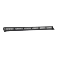
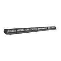
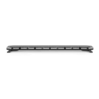
The STRIKER® 6 Traffic Advisor is a professional-grade emergency warning device designed to alert pedestrians and other operators to the presence of personnel, emergency vehicles, or an emergency site. It is crucial for users and installers to read the entire manual to ensure proper and safe operation, preventing potential property damage or serious injury.
The STRIKER® 6 Traffic Advisor is intended to provide visual warning signals. It features a variety of flash patterns, including both warning patterns and traffic advisor patterns. The warning patterns offer different flash rates and sequences, such as Steady Burn, Triple Flash Left/Right, Single Flash Outside In, and various alternating and quad flash options. The traffic advisor patterns are designed to direct traffic flow, offering Left Arrow, Center Out Arrow, and Right Arrow sweeps with different stacking and pulsing options. The device incorporates non-volatile memory, which recalls the last selected flash pattern when the unit is powered on.
The STRIKER® 6 Traffic Advisor can be operated using a Direct Control Switch Box (sold separately). This control box includes a Power Button to turn the unit On/Off, a Flash Mode Button to switch between Traffic Advising mode and Warning mode, and dedicated Traffic Advisor Buttons for Left Arrow, Center-Out, and Right Arrow sweeps. A Flash Pattern Button allows users to cycle through the various flash patterns. Holding this button for 3 seconds toggles Steady Burn mode, while holding it for 5 seconds toggles Random pattern mode. A Slow/Fast Slide Switch adjusts the flashing speed. Additionally, an AUX Button on the control box toggles power to AUX cables On and Off. It's important to note that the Power Button on the control box does not need to be activated for the other buttons to function.
For installations requiring extended reach, an Extension Cable (sold separately) can be used. If the extension cable has connectors, they should be connected to the corresponding ends. If the extension cable has one connector, the connector from the main cable harness of the Light Bar will need to be cut off, and the wires soldered and heat-shrunk to the extension cable wires. If the extension cable has no connectors, the main cable harness will need to be cut, and the wires soldered and heat-shrunk to the extension cable wires. It is crucial not to cross connect wires and to ensure that connectors, cables, and solder points are not exposed to heat, moisture, or debris.
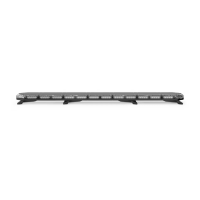
The STRIKER® 6 Traffic Advisor offers various mounting options (sold separately) to suit different vehicle configurations:
Before installation, all units should be bench tested by connecting the Positive Cable (Red) and Negative Cable (Black) to a power source. This ensures that all features and parts, including LED diode and module functionality, flash patterns, non-volatile memory, and physical condition, are working correctly.
To preserve the longevity and function of the STRIKER® 6 Traffic Advisor, certain maintenance practices are recommended:
It is critical to ensure proper installation and mounting. The equipment must be securely attached to a part of the vehicle strong enough to withstand applied forces. Mounting within airbag deployment areas or routing wires through these areas must be avoided to prevent serious personal injury and maintain airbag effectiveness. If drilling is required, ensure no vehicle components are damaged, deburr all holes, and remove metal remnants. Grommets should be used in all wire passage holes. Wiring should be anchored and protected using grommets, cable ties, and looms. Fuses, properly sized and located close to the power take-off points, are essential for protecting the wiring and device from short circuits. Never use a fuse with a higher amp rating than the initial fuse provided. Insulation displacement connectors should not be used. A secure electrical connection to the battery's Ground Post (specifically the NEGATIVE (-) battery post) is necessary for optimum efficiency; circuit breaks should not be used. Instruction manuals should be stored in a safe place for future reference or can be found online. Control boxes or remote devices should be installed in a location that allows safe operation without distracting the user. Wires in the engine compartment should be SXL type for higher heat resistance, in accordance with SAE J-1128, and protected from hot surfaces and moving parts. Failure to follow these safety precautions, warnings, notices, and instructions can void the warranty and cause serious injury.
| Flash Patterns | 26 |
|---|---|
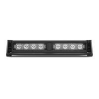
| Number of Lightheads | 6 |
| Lighthead Type | Linear |
| Housing Material | Aluminum |
| IP Rating | IP67 |
| Color Options | Amber, Blue, Red, White, Green |
| Mounting Type | permanent, or magnetic |
| Operating Voltage | 12V DC |
| Voltage | 12V DC |
| Control Options | Wired Controller |