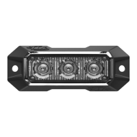
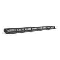
The SpeedTech Lights Z-3 is a compact grille/surface mount LED warning light designed for emergency vehicles. It is available in two models, G-ZTC3 and G-ZLC3, and is intended to alert pedestrians and other drivers to the presence of emergency personnel or vehicles.
Function Description
The Z-3 unit provides visual warning signals through its LED modules. It supports both synchronized and alternating flash patterns, allowing for flexible configuration based on warning needs. The device is designed for professional use by authorized personnel and requires proper installation to ensure optimal performance and safety.
Important Technical Specifications
- Voltage: 12 VDC
- Amps: < 0.25 A
- Optic: TIR / Linear
- LED Count: TIR: 3 / Linear: 3
- Cable Length: 1 foot
- Flash Patterns: 13
- Dimensions: Approximately 3.2 inches long, 1.2 inches high, and 0.6 inches deep.
Wiring Diagram
The Z-3 unit features a multi-color wiring system for various functions:
- Red (main power cable): Positive (+12 VDC)
- Black (main power cable): Negative (Ground)
- Yellow: Flash Pattern (contact +12 VDC to cycle through patterns)
- Green: Steady Burn Override (contact +12 VDC for steady burn mode)
- White: Sync (connects units for synchronization)
- Blue: Alternating Sync Programming (contact +12 VDC for alternating synchronization)
Note: All cables except Negative and Sync require contact with +12 VDC for their respective functions.
Flash Pattern List
The Z-3 offers 13 distinct flash patterns, including:
- Steady Burn
- Single Flash 90 FPM
- Single Flash 210 FPM
- Triple Flash 60 FPM
- Single Flash 240 FPM
- Single Flash 120 FPM with Burst
- Triple Flash 90 FPM
- Quad Flash 90 FPM
- Single Flash 60 FPM
- Single Flash 150 FPM
- Single Flash 60 FPM with Burst
- Accelerating Single Flash
- Single Flash 45 FPM
Flash Pattern Shortcuts
- Steady Burn: Hold the Flash Pattern wire (Yellow) to +12 VDC for 3 seconds to toggle Steady Burn mode.
- Non-volatile Memory: All STL LED products are equipped with non-volatile memory, which recalls the last selected flash pattern when the product is turned on.
Usage Features
Mounting Options
The Z-3 offers several mounting configurations, with some brackets sold separately:
-
Surface Mounting w/ Foam Backing Pad (Included):
- Run the cable through the central hole of the foam pad.
- Use the included hardware to mount the unit directly to the vehicle surface.
-
Double Stack Z Flange Mounting Bracket (Sold Separately):
- Seats two Z-3 units into the flange.
- Run cables through the central holes of the foam pad.
- Use the hardware included with the Z-3 units to mount the assembly to the vehicle.
-
Static Mounting Bracket (Sold Separately):
- Run the cable through the foam pad and bracket central holes.
- Use the hardware included with the bracket to secure the unit to the bracket.
- Available in Single Static Bracket, Dual Static Vertical Bracket, and Dual Static Horizontal Bracket configurations.
-
License Plate Mounting Bracket (Sold Separately):
- This kit includes hardware and three metal pieces (two short, one long).
- Connect the two short pieces to the long piece using the included hardware.
- Run the Z-3 unit cable through the foam pad and short piece central holes.
- Secure a Z-3 unit to each short piece using the included hardware.
- Mount the entire assembly to the vehicle using the same hardware that secures the license plate.
- Lights can be configured to hang vertically or horizontally.
Synchronization
The Z-3 units can be synchronized to flash in unison or in an alternating pattern.
Extension Cable (Sold Separately)
If extending the main cables, add the desired length of cable to the unit's main cables. Solder and heat shrink the wire connections. Avoid cross-connecting wires and ensure connectors, cables, and solder points are protected from heat, moisture, or debris.
Maintenance Features
- Cleaning: Use only water (H2O) with a soft cloth to clean the outer body and lenses. Never use a pressure washer or take the unit through a car wash, as chemicals, high-pressure water, or brushes can scratch or damage the equipment.
- Lens Yellowing: Yellowing of clear lenses may occur over time. Replacement lenses can be purchased by contacting STL Customer Service.
- Daily Inspection: Inspect and test the product daily to ensure it operates properly and is mounted correctly.
- Troubleshooting: If issues arise, contact STL's Customer Service for troubleshooting options or warranty claims.
- Manual Storage: Keep the instruction manual in a safe place for future reference or access it online at www.SpeedTechLights.com.
Safety Warnings and Notices
- Read Manual: Users and installers must read the entire manual before operating or installing any STL product to prevent property damage and/or serious injury.
- LED Staring: Never stare directly into the LEDs, as this may cause momentary blindness or eye damage.
- Power Disconnection: Never cut wires or work on the unit while it is connected to a power source.
- Airbag Deployment Area: Do not install this product or route wires through or in the airbag deployment area. This can cause serious personal injury by damaging or reducing airbag effectiveness or turning the unit into a projectile. Consult your vehicle's owner's manual for airbag deployment areas.
- Drilling: If drilling is required, ensure no vehicle components or vital parts are damaged. Deburr all drilled holes and remove metal remnants. Install grommets in all wire passage holes.
- Wiring Protection: Use grommets, cable ties, and looms to anchor and protect all wiring.
- Fuses: Fuses must be properly sized and located as close to the power take-off points as possible. Do not use a fuse with a higher amp rating than the initial fuse included by STL. Insulation displacement connectors are not to be used.
- Grounding: Ensure a secure and good electrical connection to the battery's Negative (-) post. Do not use circuit breaks.
- Control Box Placement: If a control box or remote device is used, install it in a location that allows safe operation by the user and vehicle in any driving condition.
- Hazardous Driving Conditions: Never activate or control equipment in hazardous driving conditions.
- Wire Type: Use SXL type wire in the engine compartment where higher heat resistance is required (according to SAE J-1128). All wires must comply with minimum wire size recommendations and be protected from hot surfaces and moving parts.
- Electromagnetic Interference (EMI): Mount Light Bars a minimum of 12" - 34" from the radio antenna. Do not power equipment from the same circuit or share the same grounding circuit with radio communication equipment. Test all vehicle equipment after installation to ensure no interference.
- Secure Mounting: All STL equipment must be mounted and installed according to vehicle manufacturer instructions and securely attached to a part of the vehicle strong enough to withstand applied forces. Permanent mounting within specified zones is crucial. Interior mounting by non-permanent methods is discouraged due to potential detachment under aggressive driving conditions.
- Professional Installation: This is professional-grade equipment. Proper installation combined with operator training in the proper use of emergency warning devices is essential for safety.
- Legal Compliance: Users are responsible for understanding and obeying all applicable city, state, and federal laws regarding emergency warning devices.
- Liability: SpeedTech Lights, Inc. assumes no liability for any loss resulting from the use of this warning device.
Pre-Installation and Testing
- Bench Test: All units must be bench tested prior to installation by connecting the Positive Cable (Red) and Negative Cable (Black) to a power source.
- Test Check List:
- LED diode and LED Module functionality
- Flash patterns
- Non-volatile memory
- Physical damage
- If any issues are found during testing, contact Customer Service at 800-757-2581.