4 SpeedTech Lights, Inc © 2019
Z
-
3
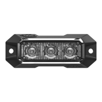
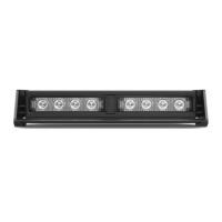
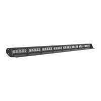
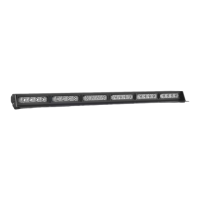
GRILLE / SURFACE MOUNT
Flash Pattern Synchronization
• Make sure all units that need to be synced together are powered On and ashing on the same pattern.
• Connect the White cables of all units to each other.
• Connect the Yellow cables of all units and contact +12 VDC to cycle all units to the next pattern.
• Power all units O and back On to complete the Sync process.
Flash Pattern Alternating Synchronization
• Make sure all units that need to be synced together are powered On and ashing on the same pattern.
• Connect the White cables of all units to each other.
• Divide the units into 2 groups and connect all the Blue cables of the rst group together.
• Connect all the Blue cables of the second group together.
• Take all the Blue cables from the rst group and contact +12 VDC for 3 seconds until all rst group units are steady burn. Only half
of each unit will light up steady burn.
• Take all the Blue cables from the second group and contact +12 VDC for 5 seconds until all second group units are steady burn.
Only half of each unit will light up steady burn. It will be the opposite half as the rst group.
• Power all units O and back On to complete the Alternating Sync process.
• NOTE: While programming, if either group steady burn portion ceases, restart program sequence from step 5.
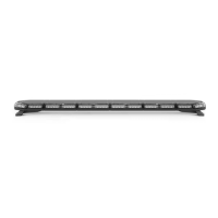
Extension Cable (Sold Separately)
• If you are extending the main cables, just add the desired length of cable to the end of the main
cables coming out of the unit. You will solder and heat shrink the wire you are lengthening from
the unit to each additional length of extension cable. DO NOT cross connect wires.
• NOTE: DO NOT leave connectors, cables, solder points exposed to heat, moisture, or debris.
Wiring Diagram
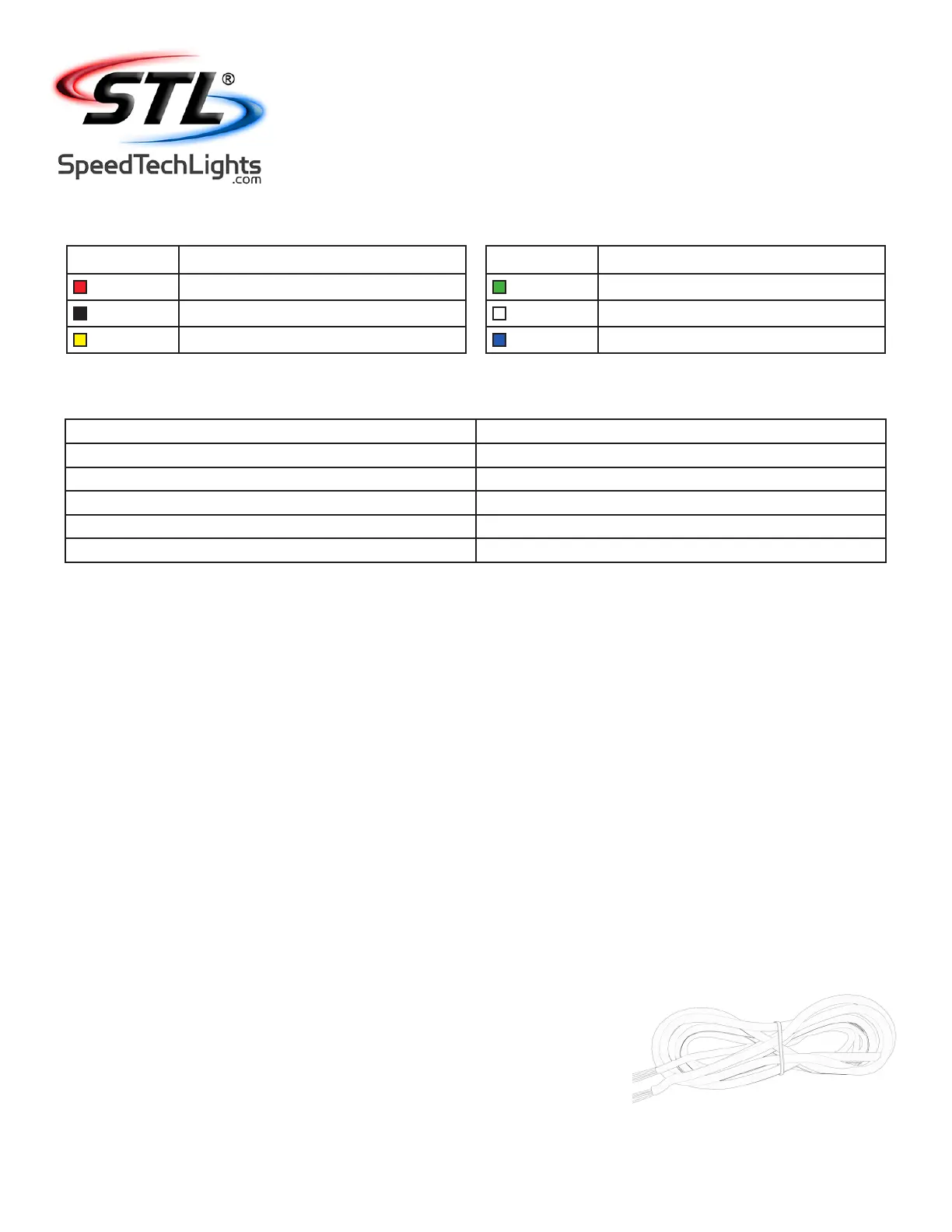
Wire Color Function
Red*
Positive
Black*
Negative
Yellow
Flash Pattern
* Indicates a main power cable.
Wire Color Function
Green
Steady Burn Override
White
Sync
Blue
Alternating Sync Programming
NOTE: All cables except Negative and Sync contact +12 VDC.
Specications
Voltage
12 VDC
Amps < 0.25
Optic TIR / Linear
LED Count TIR: 3 / Linear: 3
Cable Length 1’
Flash Patterns 13