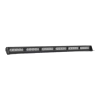
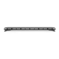
The STRIKER® 6 Traffic Advisor is a professional-grade emergency warning device designed to alert pedestrians and other operators to the presence of personnel, emergency vehicles, or an emergency site. It is crucial for users and installers to thoroughly read the instruction manual to ensure proper and safe operation, as it contains vital information to prevent property damage and serious injury.
Function Description:
The STRIKER® 6 Traffic Advisor provides visual warning signals through its LED modules. It offers a variety of warning flash patterns and specific traffic advisor patterns, including left arrow, center-out arrow, and right arrow sweeps, to guide traffic effectively. The device is equipped with non-volatile memory, which recalls the last selected flash pattern when powered on. For enhanced control, an optional Direct Control Switch Box (sold separately) can be used to manage power, flash patterns, and traffic advisor functions.
Usage Features:
- Daily Testing: The device and all its functions should be tested daily to ensure correct operation. Any malfunctions should be reported to customer service immediately.
- Unobstructed Signal: Ensure that the visual signal is not blocked by vehicle components (e.g., open trunks, visors, compartment doors), other obstructions, or people.
- Authorized Use: This equipment is intended for strict use by authorized personnel only. Users are responsible for understanding and obeying all applicable city, state, and federal laws and regulations regarding emergency warning devices.
- Safe Installation: Proper installation and mounting are critical for the device's effectiveness and safety. Controllers should be installed within convenient reach of the operator to maintain eye contact with the roadway. Improper wiring and mounting can reduce output and performance.
- Electrical Safety: Emergency warning devices often require high electrical voltages and/or currents. Users must protect and use caution around live electrical connections. Grounding or shorting can cause severe personal injury or vehicle damage, including fire. Fuses, properly sized and located as close to the power take-off points as possible, are included to protect against short circuits.
- Electromagnetic Interference (EMI): To prevent EMI, light bars should be mounted a minimum of 12" - 34" from the radio antenna. Avoid powering the equipment from the same circuit or sharing the same grounding circuit with radio communication equipment. After installation, all vehicle equipment should be tested together for interference-free operation.
- Airbag Safety (SRS): Equipment must not be installed in the deployment area of airbags, as this can damage or dislodge airbags and sensors, reducing their effectiveness and potentially causing serious injury. Refer to the vehicle's owner's manual for airbag deployment areas.
- Secure Mounting: All equipment must be mounted and installed according to the vehicle manufacturer's instructions and securely attached to a part of the vehicle strong enough to withstand the forces applied by the equipment. Permanent mounting is recommended, especially for exterior units, to prevent detachment under aggressive driving conditions.
- Pre-Installation Bench Test: Before installation, all units should be bench tested by connecting the Positive Cable (Red) and Negative Cable (Black) to a power source to ensure all features and parts are functional. This includes checking LED diode and module functionality, flash patterns, non-volatile memory, and for any physical damage.
- Wiring Diagram: The manual provides a detailed wiring diagram for connecting the main power cables (Red for Positive, Black for Negative, Brown for Power) and function cables (Yellow for Flash Pattern, Purple for Flash Mode 1, Green for Left Arrow, Orange for Center Out Arrow, Blue for Right Arrow, Grey for Slow/Fast, Light Blue for Flash Mode 2). All cables except the Negative contact +12 VDC.
- AUX Wiring Diagram: An AUX wiring diagram is provided for additional functions, including AUX Positive (Red), AUX Negative (Blue), and Control Box Backlight (White), which is functional only with the STL Direct Control Box (sold separately).
- Direct Control Switch Box (Sold Separately):
- Power Button: Turns the Direct Control Box On/Off.
- Mode 1 Button: Activates warning function in flash pattern memory 1.
- Mode 2 Button: Activates warning function in flash pattern memory 2.
- Traffic Advisor Buttons: Provides Left Arrow (Right to Left sweep), Center-Out (Center-Out sweep), and Right Arrow (Left to Right sweep) functions.
- Flash Pattern Button: Cycles to the next flash pattern with each press. Non-volatile memory recalls the last pattern. Holding for 3 seconds toggles Steady Burn mode; holding for 5 seconds toggles Random pattern mode.
- Slow/Fast Slide Switch: Adjusts flashing speed.
- AUX Button: Toggles power to AUX cables On and Off.
- Night Button: Activates backlight LEDs in the control box. Note: The Power Button does not need to be activated for AUX and Night buttons to function. The Night button can be hardwired to the headlight +12VDC line for automation, in which case the button itself ceases to function. Ensure the Night button is not toggled before hardwiring to prevent constant activation.
- Extension Cable (Sold Separately): Instructions are provided for connecting extension cables, whether they have connectors or require cutting and soldering. It is crucial to solder and heat shrink each wire properly and avoid cross-connecting wires. Connectors, cables, and solder points must not be exposed to heat, moisture, or debris.
- Mounting Options:
- 90° Suction Cup Bracket: Slide track screws secure the unit to the bracket. Suction cups attach to the bracket, and screws secure the unit into the suction cup. Do not moisten suction cups prior to application.
- 360° Suction Cup & L-Brackets: Remove standard end caps. Secure suction cup end caps using screws from standard end caps. Attach the bracket to the end caps using included hardware. Secure the suction cups to the brackets. Fasten included screws into suction cup. The bracket can be used for permanent mounts by not attaching the suction cups and using the oval mounting tracks. Do not moisten suction cups prior to application.
- Surface Mount End Caps: Remove standard end caps. Replace with Surface Mount End Caps using screws from standard end caps.
- Headliner Mounting Bracket: The Static Headliner Bracket is a solid piece. Slide track screws secure the unit to the bracket. The Adjustable Headliner Bracket includes 1 base bracket and 1 J-bracket. Slide track screws secure the unit to the base bracket. The J-bracket attaches to the base bracket. Slide track screws secure the unit to the J-bracket.
- Static Mounting Bracket: Slide track screws secure the unit to the bracket with the bracket oval tracks.
- Windshield Visor Assembly and Mounting: Remove stock end cap screws from both ends of the Light Bar (save for non-visor configuration). Secure two visor end caps onto both ends of the visor using six short screws. Secure the visor assembly to the Light Bar using four long screws included with the windshield visor.
Maintenance Features:
- Cleaning: Never take STL Light Bars through a car wash, including pressure washers, automatic car washes, or washes with brushes or chemicals that could scratch or damage the equipment. Use only water with a soft cloth to clean the Light Bar and lenses.
- Lens Yellowing: Yellowing of clear lenses may occur over time. Replacement lenses can be purchased by contacting STL Customer Service.
- Wire Protection: Use grommets, cable ties, and looms to anchor and protect all wiring.
- Instruction Manual Storage: Keep instruction manuals in a safe place for future reference or maintenance. They are also available on the SpeedTech Lights website.