5 | Installation
16
07/2023 | ID 443360_en.00
5.2.1 Permitted tilting torques at the gear unit input
If you mount a STOBER gear unit on the machine in a horizontal mounting position, check that the permitted tilting torque
is not exceeded on the gear unit input before mounting the corresponding motor. Information on the permitted tilting
torque can be found in the corresponding catalog (Additional documentation [}12]).
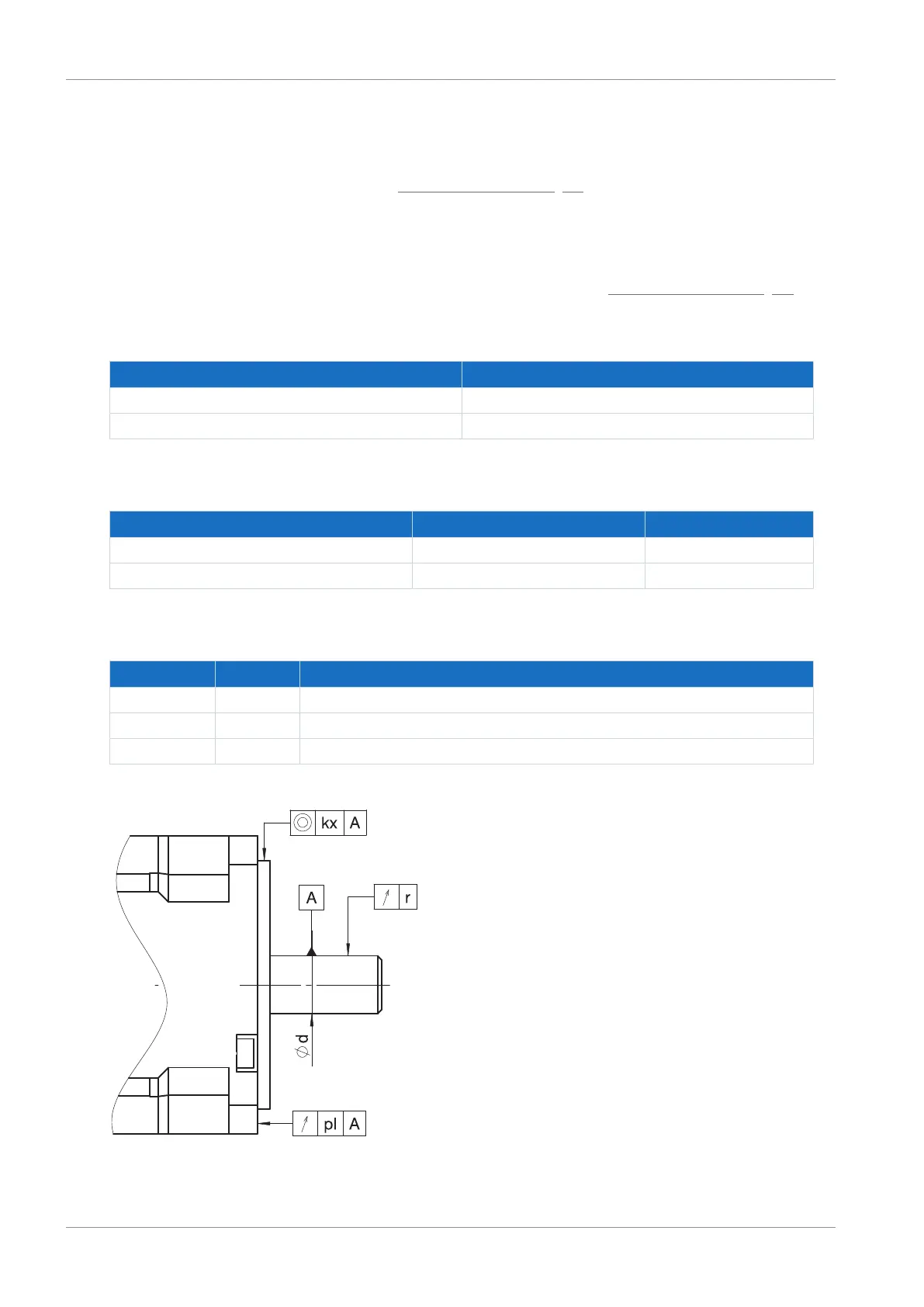
5.2.2 Tolerances for the add-on motor
This chapter describes tolerances for motors that are required for assembly on a STOBER gear unit with motor adapter.
Dimensional drawings of the motor adapter can be found in the corresponding catalog (Additional documentation [}12]).
Tolerances for shafts in accordance with DIN 748-1
Diameter [mm] Tolerance
≤ 50 ISO k6
> 50 ISO m6
Tolerances for centering diameter on the motor flange in accordance with EN 50347
Centering diameter [mm] Flange size [mm] Tolerance
≤ 230 65 – 300 ISO j6
> 230 350 – 500 ISO h6
Tolerances for radial runout, axial runout and concentricity in accordance with IEC 60072-1 (normal class)
Symbol Unit Explanation
kx µm Concentricity of the flange centering in relation to the shaft
pl µm Axial runout of the flange mounting surface in relation to the shaft
r µm Radial runout of the shaft end