5 | Installation
22
07/2023 | ID 443360_en.00
Procedure
1. Position the gear unit so that the nameplate of the gear unit is still visible after mounting.
2. Center the gear unit in the connecting structure using the pilot of the gear housing.
3. Mount the output flange of the gear unit to the connecting structure using screws. Details on the screws can be found
in the following table.
4. Tighten the screws evenly in multiple passes with increasing torque and alternating diagonally. The tightening torques
can be found in the chapter Tightening torques [}23].
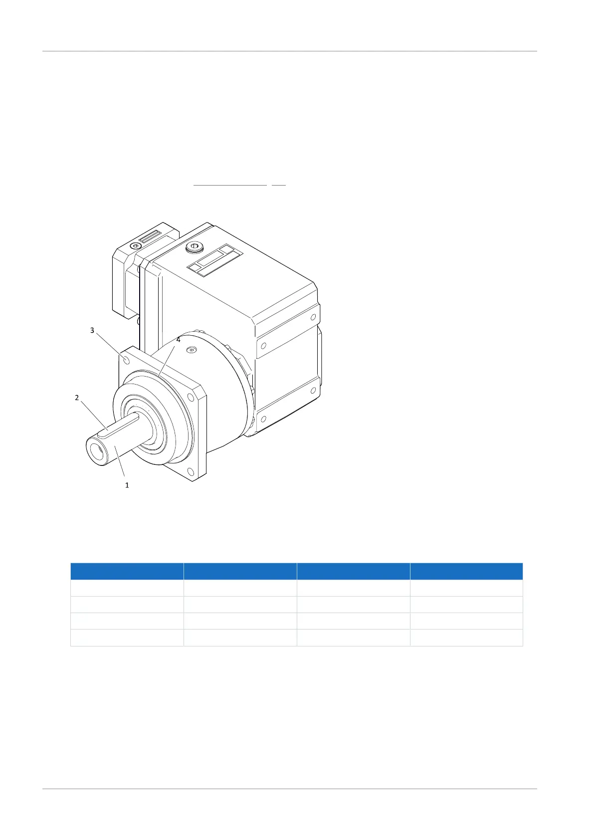
1 Solid shaft 2 Feather key (if present)
3 Output flange bore 4 Housing pilot
Gear unit type Number of screws Screw size Strength class
P5_K 4 M8 12.9
P7_K 4 M10 12.9
P8_K 4 M12 12.9
P9_K 4 M16 12.9
Tab. 1: Information on screws for mounting the gear housing on the machine