STOBER 8 | Connection
03/2020 | ID 442793.03
69
8.4.22 Connecting a drive controller
WARNING!
Electrical voltage! Risk of fatal injury due to electric shock!
▪ Always switch off all power supply voltage before working on the devices!
▪ Note the discharge time of the DC link capacitors in the general technical data. You can only determine the absence
of voltage after this time period.
Tools and material
You will need:
§ A suitable terminal set for the drive controller
§ Tool for tightening the fastening screws
Requirements and connection
Bottom of the device:
ü
You have a system circuit diagram describing the connection of the drive controller.
1. Optional: Connect the braking resistor to terminal X21 and attach the terminal. Make sure that the conductors are
twisted pairs.
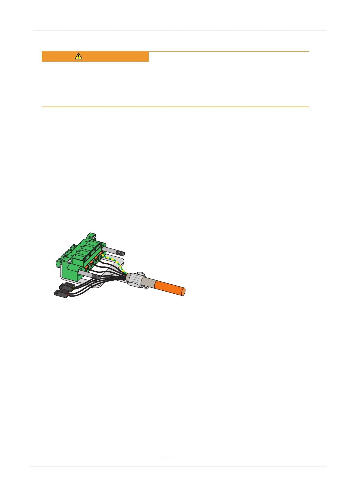
2. In order to connect the motor temperature sensor, the control of the brake and the motor itself to the drive
controller, wire the cores of the power cables with terminals X2A and X20A.
3. Attach the power cable with the shield clamp to the shield contact of terminal X20A.
4. Attach terminals X20A and X2A and tighten the screws of X20A.
5. Optional: Connect the supply voltage for the brakes to terminal X300 and attach it.
6. For double-axis controllers: Repeat steps 2 to 4 for the terminals X2B and X20B.
7. Optional: Connect an encoder to terminal X4A.
8. Optional for double-axis controllers: Connect an encoder to terminal X4B.
Top of the device:
ü
There is a circuit diagram of the system that describes the connection of the drive controller.
1. Connect the power supply to terminal X10 and attach the terminal.
2. Connect the 24V
DC
power supply for the control electronics to terminal X11 and attach the terminal.
3. If you use the STO safety function, connect it as follows:
3.1. SR6 option: Connect terminal X12 according to your safety configuration.
3.2. SY6 option: In order to be able to identify the safety module in the FSoE network, you must transfer its unique
address in the FSoE network to the drive controller using the DIP switches.
4. Optional: Connect the digital inputs to terminals X101 and X103 and attach the terminals.
5. Connect the fieldbus to the sockets X200 and X201.
You can find examples in the chapter Wiring examples [}89].
 Loading...


