2971-022-188
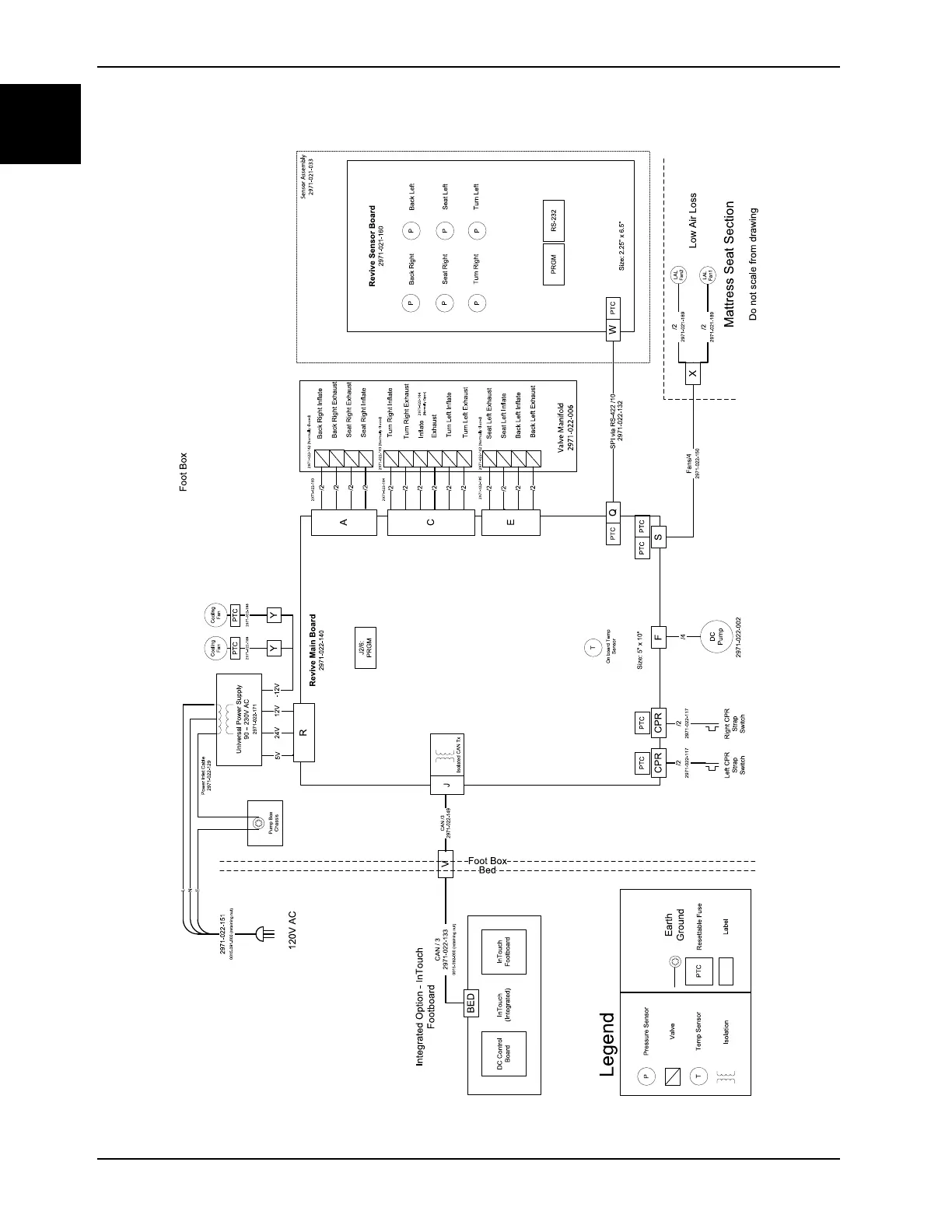
Revive Main Board
2971-022-140
Size: 5" x 10"
DC
Pump
T
Revive Sens or Board
2971-021-160
Size: 2.25" x 6.5"
P
P
P
P
Back Right
Back Left
Seat Right
Seat Left
PP
Turn Left
Turn Right
Inflate
Back Left Inflate
Seat Left Inflate
Turn Left Exhaust
Back Right Inflate
Seat Right Inflate
Turn Right Exhaust
Exhaust
Foot Box
Foot Box
CAN / 3
2971-022-133
0015-092-000 (re taining nut)
Right CPR
Strap
Switch
/2
2971-022-117
LAL
Fa n1
LAL
Fa n2
Back Left Exhaus t
Back Right Exhaust
Turn Left Inflate
Turn Right Inflate
Seat Left Exhaust
Seat Right Exhaust
J2/6:
PRGM
/2
/2
/2
/2
/2
/2
/2
/2
/2
/2
/4
Fa ns/4
2971-022-150
SPI via RS-422 /10
Q
CAN /3
2971-022-149
PRGM RS-232
InTouch
(Integrated)
24V
5V
Integrated Option - InTouch
Footboard
Pressure S ensor
P
Legend
Temp Sensor
T
Valve
12V
Bed
Left CPR
Strap
Switch
/2
2971-022-117
/2
/2
/2
/2
R
J
2971-022-132
2971-022-002
Valve Manifold
2971-022-006
Mattress Seat Section
/2
2971-021-189
/2
2971-021-189
Earth
Ground
FCPR SCPR
X
W
C
A
E
V
L
N
E
Power Inlet Ca ble
2971-022-129
Pump Box
Chass is
Universal Power Supply
90 – 230V AC
2971-022-171
On board Te mp
Sensor
Isolation
Isolated CAN Tx
BED
Do not scale from drawing
Sensor Assembly
2971-021-033
2971-022-162 (Normally Closed)
2971-022-163 (Normally Closed)
2971-022-162 (Normally Closed)
2971-022-164
(Norma lly Ope n)
PTC
PTCPTC PTC
PTC
Re settable Fuse
PTC
2971-022-185
2971-022-184
2971-022-183
2971-022-151
0015-091-000 (re taining nut)
Cooling
Fa n
-12V
Y
PTC
Label
120V AC
PTC
Low Air Loss
DC Control
Boa rd
InTouch
Footboard
2971-022-188
Cooling
Fa n
Y
PTC