Do you have a question about the Stryker Secure II and is the answer not in the manual?
Instructions for setting and releasing the central bed brakes.
LED lights indicate brake engagement status for safety.
How to move the steer pedal located at the head end of the bed.
Steer caster guides bed straight and aids cornering when activated.
Outlet reduces cords, preventing trip hazards.
Night lights turn off automatically if ambient room light is sufficient.
Squeeze red handles to quickly lower Fowler to flat position.
Instructions for using the optional CPR board or headboard.
Optional hooks do not affect patient weight readings on the scale.
Press yellow release button to lower siderails.
Push handle and rotate to lock siderails in intermediate position.
Positions patient's hips correctly on the bed in intermediate mode.
Provides grip points for patients to assist with egress.
Step-by-step guide to zero the scale before weighing a patient.
Select units (lb or kg) for scale information display.
Add or remove bed items without affecting patient weight.
Procedure to arm the Chaperone Bed Exit System.
Procedure to deactivate the Chaperone Bed Exit System.
Allows free movement; alarms when 50% body weight leaves the zone.
Alarms when patient approaches siderail or foot end.
Alarms when patient leaves the tightly restricted zone.
Describes light bar states (Green, Amber) and footboard display.
Display and LED indicators for low height state changes.
Display and LED indicators for disengaged brakes.
Display and LED indicators for siderail position changes.
Display and LED indicators for disarmed bed exit.
Positions Fowler to 30° and locks motion below 30°.
Setting audible alarms and alarms to Nurse Call Station.
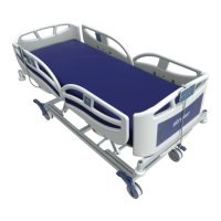
This document provides a quick start guide for the Stryker Secure® II Medical bed, outlining its key features, operational procedures, and safety considerations.
The Stryker Secure® II bed includes several components for patient comfort and caregiver control. The Headboard (A) and Footboard (E) define the ends of the bed. Siderails (C) are positioned along the sides, offering patient security and housing some controls. Patient Controls (B) are accessible to the patient, while the Nurse Control Panel (D) provides comprehensive control for caregivers. For mobility, the bed is equipped with Casters (G). An optional 120V AC Outlet (F) is available for powering medical devices, and a Siderail Release Handle (H) allows for easy adjustment of the siderails. The bed's braking and steering mechanisms are controlled by the Brake Pedal (I) and Steer Pedal (K), respectively, with Siderail Controls (J) integrated for convenience.
The bed features centrally located brakes designed for ease of use and patient safety. To activate the brake, press the Brake Pedal (I) once. Pressing it again will release the brake. For enhanced safety, LED lights on the outside of the head-end siderails and on the foot-end control panel will blink when the brakes are not engaged, providing a visual alert. It is crucial to always apply the caster brakes when a patient is getting on or off the bed, and to push on the bed to ensure the brakes are securely locked. Engaging the brakes is necessary unless the bed is being moved, as movement while a patient is getting on or off could result in injury.
The Steer Pedal enhances the bed's mobility, particularly when navigating hallways or tight spaces. To activate the steer function, move the pedal located at the head end of the bed. When activated, the steer caster helps guide the bed along a straight line and facilitates pivoting around corners. A safety warning advises against attempting to move the foot end of the bed laterally when the steer pedal is activated, as the steer caster at the foot end cannot swivel in this mode, and attempting to do so may cause injury to the user.
An optional 110V AC outlet is located under the footboard at the foot end of the bed. This outlet has its own power cord that must be plugged in separately. Its primary function is to reduce the number of cords strung across the room, thereby removing a potential trip hazard and contributing to fall prevention. Safety guidelines specify that only equipment with electrical specifications of 110 VAC, 10A, and 60Hz should be used. The maximum total load drawn by equipment in this receptacle must not exceed 10A, and the total system chassis risk current should not exceed 300uA. Grounding continuity should be checked periodically. To avoid electric shock, all power cords must be unplugged before opening the service compartment, junction box, or receptacle. The optional 110V outlet is not to be used for life-sustaining equipment.
The bed is equipped with two night lights that illuminate the floor area around the bed, aiding in fall prevention during low-light conditions. The switch for these lights is located under the litter thigh section on the patient's left side. This switch turns both lights on and off. For added convenience and energy efficiency, the night lights feature a sensor that will automatically turn them off if the ambient light in the room is bright enough, eliminating the need for a night light.
In situations requiring cardiopulmonary resuscitation (CPR), the bed offers an emergency CPR release mechanism. If the bed's fowler is raised, squeezing one of the two red release handles will quickly guide the fowler down to a flat position. The handle can be released at any time to stop the fowler from lowering, providing controlled descent.
For beds equipped with the optional CPR board, it is stored on the bed's headboard. To remove it, pull it away from the headboard and lift it out of its storage position. If the CPR board option was not purchased, the headboard itself can be removed and used as an emergency CPR board.
Foley bag hooks are strategically placed at two locations on both sides of the frame: under the frame below the seat section and at the foot end of the frame. Additionally, optional isolated Foley bag hooks are located at the foot end of the bed on top of the lift header. A key ease-of-use feature is that the patient weight reading on the scale system will not be affected when the optional isolated Foley bag hooks are used, ensuring accurate weight measurements.
The siderails offer multiple positions for patient safety and caregiver access. To lower the siderails, press the yellow release button. Grasp the top of the rail, pull outward, and swing it up to full height to raise it. Note that when raised, the siderail does not lock in an intermediate position. To utilize the intermediate position, push in the yellow release handle and rotate the siderail until it locks into place. To fully lower the siderails, push the release handle again and rotate the siderail until it is completely lowered. It is essential to ensure the siderail is locked securely into position. Siderails are designed to prevent patients from inadvertently rolling off the bed, not to keep them from exiting. Proper restraint methods should be used to ensure the patient remains in the bed, and siderails should not be used as a push device.
The BackSmart® Intermediate Siderails offer two key features: BackSmart Seat Assist and BackSmart Stand Assist. The BackSmart Seat Assist utilizes an intermediate position that places the patient's hips in the correct position on the bed, facilitating easier movement and positioning. The BackSmart Stand Assist is an integrated lift system that provides patients with two sturdy grip points, assisting them with egress (getting out of the bed).
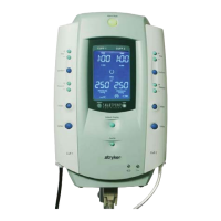
The Nurse Control Panel provides comprehensive control over bed motion.
A safety note indicates that individual beds may have different options, and footboards should not be moved from one bed to another, as mixing footboards could result in unpredictable bed operation.
The bed motion locks provide enhanced safety and control over bed movements.
To unlock any of these functions, press and hold the corresponding lock button. The button and LED on the dashboard will illuminate when activated.
To ensure accurate patient weight measurements, the bed's scale system must be zeroed prior to weighing.
A safety note warns that scale function may be affected by siderail/caster interference. When the litter is fully lowered or in Reverse Trendelenburg, and the siderails are tucked under the litter in the storage position with the casters turned, there is potential for interference. Raising the siderails when lowering the litter to the full down position can prevent this interference and ensure accurate scale readings.
To weigh a patient using the integrated scale:
Pressing the scale button again within 60 seconds of the first press will remove the data from the screen. Important safety considerations include: not zeroing bed scales or weighing patients with Percussion, Vibration, Rotation, or Turn Assist active, as patient motion and position from dynamic therapy mattresses can adversely affect scale system performance. The power save mode activates after one hour on battery power without motion release switch activation, disabling functions like Bed Exit, Scale, and Motion. This could lead to patient injury if proper monitoring protocols are not observed. For powered mattress replacement systems like XPRT, confirm proper scale system operation after mattress installation and secure the mattress power cord to prevent damage and interference with the bed frame and scale system.
The Main Menu provides access to additional features, including changing scale units and managing equipment.
This feature allows the operator to select the desired unit of measurement (pounds or kilograms) for the scale display.
This feature allows caregivers to add or remove items from the bed without affecting the patient's weight measurement.
The Chaperone® Bed Exit System is a three-zone patented center-of-gravity system that tracks a patient's body weight and alarms when 50% of their body weight exits the perimeter of the bed.
It is important to note that if the bed was not zeroed at patient admission, prior to arming, the Chaperone Bed Exit System will not operate properly. The Bed Exit System is intended only to aid in the detection of a patient exiting the bed and is not a replacement for patient monitoring protocols. It signals when a patient is about to exit. Adding or subtracting objects from the bed after arming the system may reduce its sensitivity. To avoid injury and ensure proper operation with a powered mattress replacement system, do not initialize ("arm") bed exit with Percussion, Vibration, Rotation, or Turn Assist active, as dynamic therapy mattress motion can adversely affect bed exit system performance. The power save mode, activated after one hour on battery power without motion release switch activation, will cause Bed Exit, Scale, and Motion functions to cease.
The Chaperone Bed Exit Alarm offers three distinct zones to customize patient monitoring based on their mobility and fall risk.
The iBed® Awareness system provides comprehensive monitoring of the bed's status and patient conditions, producing alerts when changes occur.
The iBed Awareness system serves as a secondary monitoring system, providing visual or audible alerts when a preset condition changes. It indicates siderail position but not if they are locked; caregivers are responsible for ensuring siderails are locked after every move and before leaving a patient. The indicator lights are an aid and do not replace caregiver responsibility for checking on patients. Nurses must physically verify siderails are locked before arming the optional iBed Awareness system.
The iBed Awareness system provides detailed monitoring and alarms for various bed states.
If the bed's low height state changes, the display will show a visual alert, and the Low Height LED on the dashboard will blink.
If the brake is disengaged, the display will show a visual alert, and the Brakes LED on the dashboard will blink.
If a siderail's position state changes, the display will show a visual alert with an arrow pointing to the siderail in alarm. The Siderail LED on the dashboard will also blink.
If the bed exit system is disarmed, the display will show a visual alert, and the Bed Exit LED on the dashboard will blink.
The Fowler 30°+ Lock button serves a dual purpose: it positions the bed's fowler to 30° (from horizontal) and locks any Fowler motion below 30°. When pressed, the bed will reposition only if it is currently below 30°. Once the bed reaches its final position, the display will read "Locked."
| Manufacturer | Stryker |
|---|---|
| Model | Secure II |
| Weight Capacity | 500 lbs |
| Bed Length | 84 inches |
| Bed Width | 36 inches |
| Caster Diameter | 5 inches |
| Side Rails | Yes |
| CPR Release | Yes |
| Dimensions | 84" L x 36" W (213 cm x 91 cm) |
| Compatibility | Compatible with standard hospital accessories |