EasyManua.ls Logo

Stryker Secure 3000 Service Manual

Stryker Secure 3000
203 pages
To Next Page IconTo Next Page
Page #1 background imageLoading...
Page #1 background image
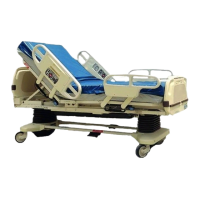
Secure 3000 Bed
MAINTENANCE MANUAL
For Parts or Technical Assistance
1–800–327–0770
IMPORTANT
File in your
maintenance
records

Table of Contents

Other manuals for Stryker Secure 3000

Questions and Answers:

Stryker Secure 3000 Specifications

General IconGeneral
BrandStryker
ModelSecure 3000
CategoryMedical Equipment
LanguageEnglish

Summary

Introduction and Specifications

Bed Specifications

Details bed specifications including weight capacity, dimensions, angles, and electrical requirements.

Warning, Caution, and Note Definitions

Defines warning, caution, and note terms used in the manual for user safety and equipment care.

Safety Tips and Guidelines

Warranty Information

Limited Warranty Details

Covers defects in material and workmanship for a specified period, and frame/weld integrity.

Obtaining Parts and Service

Information on contacting Stryker for support, parts, and service representatives.

Extended Warranty Coverage Options

Details on available extended warranty plans for parts and labor.

Return Authorization and Damaged Merchandise

Procedures for returning merchandise and filing claims for damaged/short-shipped items.

International Warranty Clause

States warranty reflects US policy; international variations may apply.

Optional Service Contract Coverage

Outlines optional service contract programs for equipment maintenance and support.

Replacement Parts List

Preventative Maintenance Procedures

Cleaning Instructions

Instructions for cleaning bed surfaces using warm water, mild detergent, and appropriate disinfectants.

Removal of Iodine Compounds

Procedure for removing iodine stains from mattress covers and foam surfaces.

Bi-Annual Maintenance Checklist

A checklist of safety features and components to inspect biannually for proper function.

Set-Up Procedures

Bed Component Illustration

Base Operation Guide

Brake Pedal Operation

Instructions on how to engage and disengage the bed's caster brakes using the foot pedal.

Steer Pedal Operation

Explanation of the steer pedal's function and how to use it for maneuverability and tracking.

Litter Operation Guide

CPR Emergency Release Usage

How to quickly lower the Fowler section using the CPR release handles for emergency access.

Foley Bag Hooks Usage

Usage instructions for standard and optional Foley bag hooks, noting impact on scale.

Foot Prop Usage

Instructions for using the foot prop to elevate a patient's feet and secure the section.

Fracture Frame Usage

Information on mounting fracture frames using I.V. sockets and compatible I.V. poles.

Optional Bed Features Operation

I.V. Poles Operation

Instructions for using permanently attached and removable I.V. poles, including height adjustment.

Night Light Usage

Operation of the optional night light, including its settings for illuminating the floor area.

Patient Restraint Strap Locations

Location of restraint strap slots and a warning about proper adjustment and use.

Head/Foot Board Operation Guide

Chart Rack Usage

How to deploy and store the optional chart rack located on the foot board.

CPR Board Usage

How to remove and use the optional CPR board stored on the head board.

Siderail Operation Guide

Siderail Positioning

Instructions for raising, lowering, tucking, and locking siderails into position, with safety warnings.

Siderail Control Panel Lights

How to activate and adjust the intensity of siderail control panel lights and nurse call lights.

Siderail Control Panel Functions

Inside Siderail Function Guide

Explains functions of buttons on the inside siderail control panels for patient controls and lighting.

Outside Siderail Function Guide

Explains functions of buttons on the outside siderail control panels for bed height and nurse call.

Dynamic Mattress System Usage

Details on setting up and using the optional Dynamic Mattress System in automatic or manual modes.

Foot Board Operation Guide

Foot Board Control Panel Guide

Explains the functions of the foot board control panel, including lights, motion lock, and position controls.

Function Lockout System Usage

How to use the lockout system to prevent unauthorized bed movement by patients or staff.

LED Display Panel Guide

Explanation of the LED indicators on the foot board display panel for power, lock status, and bed exit.

Center of Gravity Bed Exit

Procedure for activating and deactivating the Bed Exit system, with warnings.

Weigh System Control Panel Guide

Explains the controls and functions of the weigh system's control panel for patient weight measurement.

Weigh System Usage Procedures

Scale Operation Before Patient Admission

Steps to prepare and zero the scale system before patient admission for accurate weight readings.

Scale Operation with Patient In Bed

Procedure for adding or removing equipment while the patient is in bed without affecting weight.

Converting Patient Weight

Instructions to convert patient weight between pounds and kilograms using the scale system.

Changing Displayed Weight Value

How to manually adjust the numerical value of the displayed weight.

Static Discharge Precautions

Static Protection Equipment

Lists the required equipment for proper static protection when servicing electronic components.

Static Protection Procedure

Step-by-step guide for implementing static protection measures before working on the bed's electronics.

Troubleshooting Guide

Main Litter Boards Identification

Identifies the CPU and Power boards in the litter and their general functions.

Siderail Troubleshooting

Troubleshooting steps for siderail issues, differentiating between single and dual siderail problems.

Foot Board Troubleshooting

Steps to troubleshoot foot board problems, including testing and checking voltages.

Bed Lift Motor Troubleshooting

Troubleshooting lift motor issues, including premature stops, running past limits, and failure to run.

Fowler and Knee Lift Motor Troubleshooting

Troubleshooting for Fowler and Knee lift motors, including cam/switch issues and motor failure.

Scale and Bed Exit System Troubleshooting

Troubleshooting the scale and bed exit system, emphasizing user issues and load cell problems.

DMS Mattress System Troubleshooting

Troubleshooting steps for the DMS mattress system, checking power, controls, and air leaks.

Nurse Call System Troubleshooting

Troubleshooting for the nurse call system, including interface issues and jumper settings.

Bed Component and Wiring Diagrams

Base Assembly Component Diagram A

Exploded view of the base assembly with components labeled A through K.

Base Assembly Component Diagram B

Exploded view of the base assembly with components labeled A through Z.

Base Assembly Parts List A-Z

Table listing part numbers and names for components A through Z in the wiring diagram.

Base Assembly Component Diagram D

Diagram showing components R, S, T, J, B, A, F, E in the base assembly.

Base Assembly Component Diagram E

Diagram showing components H, P, M, N, L, J, K, G, O in the base assembly.

Base Assembly Parts List A-T

Table listing part numbers and names for components A through T in the wiring diagram.

Lift Motor and Coil Cord Diagram

Diagram showing power coil cord, sensor coil cord, lift motor, capacitor, and potentiometers.

Bed Circuit Boards Information

CPU Board PCB – P/N 3001–307–910 Details

Details of the CPU board, including connector locations, voltage, and pin assignments.

CPU Board PCB Continued (Load Cells, Lift Pots)

Continued details of the CPU board, listing connector locations, voltage, and pin assignments for load cells and lift pots.

CPU Board PCB Continued (Siderail, Brake Switch)

Further details of the CPU board, covering load cells, lift pots, brake switch, and siderail connections.

CPU Board PCB Continued (Siderail, Power Board)

CPU board connectivity to siderails and power board for motion interrupt and bed up/down functions.

CPU Board PCB Continued (Power Board Functions)

CPU board connections to the power board for various bed functions like bed up/down, Fowler, and safety relay.

Headwall Interface PCB – P/N 3001–303–900

Details of the headwall interface PCB, including connector locations, voltages, and functions like Nurse Call.

37-Pin Connector Pinout

Pinout and function description for the 37-pin connector used for external interfaces.

Head Wall Interface w/Stryker Port PCB

Details of the head wall interface PCB with Stryker port, listing connectors and functions.

Power Board PCB – P/N 3001–300–910 Details

Details of the power board, including connector locations and voltage outputs for bed motors and CPU.

Power Board PCB Continued (Motor, Cord, Fuses)

Continued details of the power board, listing connections for bed motors, power cord, and fuses.

DMS Power Supply PCB Details

Details of the DMS power supply PCB, including main power and DMS port connections.

Serial Interface PCB – P/N 3000–300–965

Details of the serial interface PCB, showing connector locations and voltage outputs for DMS.

Base Maintenance Procedures

Brake Pedal Replacement

Step-by-step instructions for replacing the brake pedal, including required tools and torque specifications.

Brake Sensor Replacement

Procedure for replacing the brake sensor switch, including tool requirements and cable management.

Steer Wheel Cable Replacement and Adjustment

Instructions for replacing and adjusting the steer wheel cable, detailing disassembly and reassembly steps.

Steer Wheel Cable Adjustment

Adjustment procedure for the steer wheel cable to ensure proper engagement and alignment.

Caster Replacement

Procedure for replacing casters, including lifting the bed and removing/installing caster nuts.

Lift Motor and Capacitor Replacement

Steps for removing and replacing lift motors and capacitors, including tool requirements and alignment notes.

Lift Motor Isolation Plate Replacement

Procedure for replacing the lift motor isolation plate, detailing component removal and reinstallation.

Lift Housing Removal and Replacement

Instructions for removing and replacing the lift housing assembly, including motor and potentiometer removal.

Lift Motor Coupler Replacement

Procedure for replacing the lift motor coupler, detailing access panel removal and coupler extraction.

Lift Potentiometer Replacement and Adjustment

Instructions for replacing and adjusting the lift potentiometer, including cable management and housing removal.

Lift Potentiometer Burn-In Procedure

Procedure to program lift potentiometers after replacement, involving diagnostic mode and limit verification.

Power and Sensor Coil Cord Replacement

Instructions for replacing power and sensor coil cords, including cable tie management and proper routing.

Litter Maintenance Procedures

Motion Interrupt Switch Replacement

Steps for replacing the motion interrupt switch, including tool requirements and system testing.

Limit Setting - Knee Motor

Procedure for setting the upper and lower travel limits for the knee motor, including cam and switch adjustments.

Cam and Cam Guide Replacement - Head and Knee Motor

Instructions for replacing the cam and cam guide for both head and knee motors, including micro switch removal.

Drive Screw and Nut Replacement - Knee Motor

Procedure for replacing the drive screw and nut for the knee motor, with detailed component breakdown.

Limit Setting - Head Motor

Procedure for setting travel limits for the head motor, including cam adjustment and caution notes.

Head Motor Removal and Replacement

Steps for removing and replacing the head motor, including tool requirements and cable management.

Head Motor Drive Isolator and CPR Decoupler Replacement

Procedure for replacing the head motor drive isolator and CPR decoupler, noting spring-loaded parts.

Drive Screw and Ball Nut Replacement - Head Motor

Instructions for replacing the drive screw and ball nut for the head motor, including access and component removal.

CPR Cable Adjustment and Replacement

Procedures for adjusting or replacing the CPR cable for proper emergency release function.

Weigh System Diagnostic Procedure

Diagnostic Mode Functions Overview

Lists the available functions within the weigh system's diagnostic mode.

Entering Diagnostic Mode

Step-by-step guide to enter diagnostic mode for the weigh system, requiring two people.

Special Key Functions in Diagnostics

Explanation of key functions within diagnostic mode for selecting load cell assemblies.

Displaying Individual Load Cell Outputs

How to display individual load cell outputs to detect defective cells.

Scale Calibration Procedure

Procedure for calibrating the weigh system using a known weight, requiring two people.

Load Cell Replacement

Load Cell Replacement Steps

Instructions for replacing load cells, including accessing the cells and proper shim installation.

Board Replacement Procedures

Power Board Replacement

Procedure for replacing the power board, including grounding, cable management, and testing.

Litter CPU Board Replacement

Procedure for replacing the litter CPU board, including grounding, cable management, and burn-in/calibration.

Main CPU Board Burn-In Procedure

Procedure for programming lift potentiometers into the CPU after board replacement.

Power Cord and Lubrication

Power Cord Replacement

Instructions for replacing the power cord, including strain relief connectors and ground wire.

Litter Grease Points

Lists specific points on the litter assembly requiring lubrication and the recommended grease types.

Siderail Maintenance Procedures

Head and Foot Siderail Cover Removal

Procedure for removing head and foot siderail covers, noting cable connections.

Molded Siderail Replacement

Steps for replacing the molded siderail, including cover removal and component reassembly.

Head End Siderail Cable Replacement

Procedure for replacing head end siderail cables, including access panel removal and cable routing.

Siderail Assembly Removal

Procedure for removing the entire siderail assembly from the bed, including cable disconnection if needed.

Foot Board Maintenance Procedures

Foot Board Hinge Removal

Instructions for removing the foot board hinge assembly or just the hinge itself.

Foot Board Module Replacement

Procedure for replacing modules within the foot board, noting the removal order and overlap precautions.

Foot Board Interface Plug Replacement

Steps for replacing the foot board interface plug, including grounding and proper orientation.

Base Assembly Diagrams and Parts

Base Assembly Diagram A

Exploded view of the base assembly with components labeled A through F.

Base Assembly Diagram B

Exploded view of the base assembly with components labeled 1 through GG, including brake link assembly.

Base Assembly Diagram C

Exploded view of the head end of the base assembly with components labeled AA through AV.

Base Assembly Diagram D

Exploded view of the base assembly with components labeled AN through BD.

Base Assembly Diagram E

Exploded view of the base assembly with components labeled BF through BH.

Base Assembly Parts List

Comprehensive list of parts for the base assembly, including part numbers, names, and quantities.

Lift Assembly (Common) Diagrams and Parts

Lift Assembly (Common) Diagram A

Exploded view of the common lift assembly with components labeled 1 through 43.

Lift Assembly (Common) Diagram B

Exploded views of lift motor, lift housing assemblies, and inner screw assembly.

Lift Assembly (Common) Parts List

List of parts for the common lift assembly, including part numbers and quantities.

Lift Assembly (Head & Foot End) Diagrams and Parts

Lift Assembly (Head & Foot End) Diagram A

Exploded view of the head/foot end lift assembly, showing components for common lift assembly.

Lift Header Assemblies Parts List

List of parts for lift header assemblies, categorized by bed type and options.

Isolation Plate Assembly Diagram

Isolation Plate Assembly Diagram A

Exploded view of the isolation plate assembly, showing isolation plate and mounting grommets.

Litter Assembly Diagrams

Litter Assembly Diagram B

Exploded view of the litter assembly, showing components for head end.

Litter Assembly Diagram C

Exploded view of the litter assembly, showing components for foot end.

Litter Assembly Diagram D

Exploded view of the litter assembly showing various mounting brackets and linkages.

Litter Assembly Diagram E

Exploded view of the litter assembly showing components on the bottom side.

Litter Assembly Diagram F

Exploded view of the litter assembly showing pivot joints and ground jumpers.

Litter Assembly Diagram G

Exploded view of the litter assembly showing Fowler link brackets and ground jumpers.

Litter Assembly Diagram H

Exploded view of the litter assembly showing Fowler litter bumpers.

Litter Assembly Diagram I

Exploded view of the litter assembly showing components and wire routing.

Litter Assembly Components

Litter Assembly Common Components

List of common components for the litter assembly, with part numbers and quantities.

Litter Assembly - 8" Shorter Bed Components

Components specific to the 8" shorter bed litter assembly.

Litter Assembly - Standard Bed Components

Components specific to the standard bed litter assembly.

Litter Assembly, Mechanical Diagrams and Parts

Litter Assembly, Mechanical Diagram A

Exploded view of the mechanical litter assembly.

Litter Assembly, Mechanical Diagram B

Further exploded view of the mechanical litter assembly.

Litter Assembly, Mechanical Diagram C

Exploded view of mechanical litter assembly components.

Litter Assembly, Mechanical Diagram D

Exploded view of mechanical litter assembly components, including section B-B detail.

Mechanical Litter Assembly Common Components

List of common mechanical components for the litter assembly, with part numbers and quantities.

Mechanical Litter Assembly - 8" Shorter Bed Components

Mechanical components specific to the 8" shorter bed litter assembly.

Mechanical Litter Assembly - Std. Bed Components

Mechanical components specific to the standard bed litter assembly.

Fowler Limit Switch Assembly

Fowler Limit Switch Assembly Diagram

Exploded view of the Fowler limit switch assembly for standard and shorter beds.

Fowler Limit Switch Assembly Parts List

List of parts for the Fowler limit switch assembly for both bed types.

Gatch Motor Assembly

Gatch Motor Assembly Diagram

Exploded view of the Gatch motor assembly with components labeled A through K.

Gatch Motor Assembly Parts List

List of parts for the Gatch motor assembly, including part numbers and quantities.

Gatch Screw Assembly Diagram and Parts

Gatch Screw Assembly Diagram

Exploded view of the Gatch screw assembly with components labeled A through AE.

Gatch Limit Switch Assembly Diagram

Gatch Limit Switch Assembly Diagram

Exploded view of the Gatch limit switch assembly with components labeled A through G.

Fowler Drive Assembly

Fowler Drive Assembly Diagram

Exploded view of the Fowler drive assembly.

Fowler Drive Assembly Parts List

List of parts for the Fowler drive assembly, including part numbers and quantities.

Lift Header Assemblies

Lift Header Assemblies Diagram

Exploded view of lift header assemblies for various bed configurations.

Lift Header Assembly - Standard Bed Parts

Parts list for the standard lift header assembly.

Lift Header Assembly - Scale Bed Parts

Parts list for the scale bed lift header assembly.

Lift Header Assembly - Scale/Foley Parts

Parts list for lift header assembly with scale and isolated Foley bag hooks.

Lift Header Assembly - Standard/Foley Parts

Parts list for lift header assembly with standard bed and isolated Foley bag hooks.

Litter Assembly, Electrical Diagrams and Parts

Electrical Litter Assembly Diagram

Exploded view of the electrical litter assembly.

Electrical Litter Assembly Diagram B

Exploded view of electrical litter assembly components, including lift sensor coil cord.

Electrical Litter Assembly Diagram C

Exploded view of electrical litter assembly components, including lift power coil cord.

Electrical Litter Assembly Diagram D

Exploded view of electrical litter assembly components in the midsection.

Electrical Litter Assembly Diagram E

Exploded view of electrical litter assembly components at the foot end.

Electrical Litter Assembly Diagram F

Exploded view of electrical litter assembly components at the head end.

Electrical Litter Assembly Standard Components

List of standard electrical components for the litter assembly, with part numbers and quantities.

Electrical Litter Assembly - 8" Shorter Bed Components

Electrical components specific to the 8" shorter bed litter assembly.

Electrical Litter Assembly - Standard Bed Components

Electrical components specific to the standard bed litter assembly.

Litter Assembly, Scale and/or Bed Exit Option Diagrams

Scale/Bed Exit Option Assembly Diagram A

Exploded view of the litter assembly with scale and/or bed exit options.

Scale/Bed Exit Option Assembly Diagram B

Exploded view of the head end of the litter assembly with scale/bed exit options.

Scale/Bed Exit Option Assembly Diagram C

Exploded views of the litter assembly's bottom and top sections with scale/bed exit options.

Scale/Bed Exit Option Assembly Diagram D

Exploded view of the foot end of the litter assembly with scale/bed exit options, showing ground jumpers.

Scale/Bed Exit Option Parts List

List of parts for litter assembly with scale and/or bed exit options, including part numbers and quantities.

Litter Assembly, 110V Outlet Option Diagrams and Parts

110V Outlet Option Assembly Diagram

Exploded view of the litter assembly with the 110V outlet option.

110V Outlet Option Components and Parts

Exploded views of the litter assembly's outlet option components and parts list.

No 110V Outlet Option Part

Part for the litter assembly when the 110V outlet option is not included.

Litter Assembly, Accessory Adapter Frame Option

Accessory Adapter Frame Option Diagram

Exploded view of the litter assembly with the accessory adapter frame option.

Accessory Adapter Frame Option Parts List

List of parts for the accessory adapter frame option, including part numbers and quantities.

Litter Assembly, DMS Option Diagrams and Parts

DMS Option Assembly Diagram

Exploded view of the litter assembly with DMS option, showing integrated and hybrid configurations.

Integrated DMS Assembly Parts List

Parts list for the integrated DMS assembly.

Hybrid DMS Assembly Parts List

Parts list for the hybrid DMS assembly.

DMS Option Assembly Diagram B

Exploded view of the litter assembly DMS option, showing component placement.

Litter Assembly, Night Light Option Diagram

Night Light Option Assembly Diagram

Exploded view of the litter assembly with the night light option.

Litter Assembly, HWI w/Communication and Ports Option

HWI w/Communication and Ports Option Diagram

Exploded view of the HWI assembly with communication and ports options.

HWI Communication Capability Diagram

Exploded view showing cable connections for HWI assemblies.

HWI w/2 Stryker Ports Parts List

Parts list for HWI assembly with two Stryker ports.

HWI w/1 Stryker & 1 Custom Port Parts List

Parts list for HWI assembly with one Stryker and one custom port.

HWI w/1 Stryker Port Parts List

Parts list for HWI assembly with one Stryker port.

HWI w/1 Custom Port Parts List

Parts list for HWI assembly with one custom port.

Litter Assembly, HWI Communication Capability Option

HWI Communication Capability Diagram

Exploded view of the HWI communication capability assembly.

Nurse Call & Comm. Assembly Parts List

Parts list for Nurse Call & Comm. assembly.

Communication Assembly Parts List

Parts list for communication assembly.

Litter Assembly, HWI Nurse Call Option Diagram

HWI Nurse Call Option Assembly Diagram

Exploded view of the HWI Nurse Call option assembly.

Head End Siderail Assembly Diagrams

Head End Siderail Assembly Diagram

Exploded view of the head end siderail assembly with inner and outer panel components.

Carrier/Arm and Glide Rod Bracket Assemblies

Exploded views of carrier/arm assembly and glide rod bracket assembly for head end siderails.

Inner Siderail Panel Assembly Diagram

Exploded views of inner siderail panel assembly for head end siderails.

Outer Siderail Panel Assembly Diagram

Exploded views of outer siderail panel assembly for head end siderails.

Left Head End Siderail Wire Routing

Diagram showing wire routing for the left head end siderail.

Right Head End Siderail Wire Routing

Diagram showing wire routing for the right head end siderail.

Head End Siderail Assembly Components

Left Standard Components

List of left head end siderail standard components.

Right Standard Components

List of right head end siderail standard components.

Left Rail - Standard Bed Components

Left rail components for standard bed.

Right Rail - Standard Bed Components

Right rail components for standard bed.

Left Rail - 8" Shorter Bed Components

Left rail components for 8" shorter bed.

Right Rail - 8" Shorter Bed Components

Right rail components for 8" shorter bed.

3001-999-1 Standard Siderail Components

Components for standard siderail.

3001-999-2 Standard Siderail w/Nurse Call Only Components

Components for siderail with nurse call only.

3001-999-3 Standard Siderail w/Nurse Call & TV/Radio Components

Components for siderail with nurse call and TV/Radio.

3001-999-4 Std. Siderail w/NC, TV/Radio, & Lights Components

Components for siderail with nurse call, TV/Radio, and lights.

3001-999-5 Std. Siderail w/NC, TV/Radio, Lights, & DMS Components

Components for siderail with NC, TV/Radio, Lights, and DMS.

3001-999-6 Std. Siderail w/NC, TV/Radio, Lights, DMS, & G/F Components

Components for siderail with NC, TV/Radio, Lights, DMS, and G/F.

3001-999-7 Standard Siderail with TV/Radio, G/F, & DMS Components

Components for siderail with TV/Radio, G/F, and DMS.

3001-999-8 Std. Siderail w/NC, TV/Radio, DMS, & G/F Components

Components for siderail with NC, TV/Radio, DMS, and G/F.

3001-999-9 Std. Siderail w/NC, TV/Radio, & DMS Components

Components for siderail with NC, TV/Radio, and DMS.

3001-999-10 Standard Siderail w/NC, TV/Radio, & G/F Components

Components for siderail with NC, TV/Radio, and G/F.

3001-999-11 Standard Siderail w/Nurse Call & Lights Components

Components for siderail with nurse call and lights.

3001-999-12 Standard Siderail w/NC, Lights, & DMS Components

Components for siderail with NC, Lights, and DMS.

3001-999-13 Std. Siderail w/NC, Lights, DMS & G/F Components

Components for siderail with NC, Lights, DMS, and G/F.

3001-999-14 Standard Siderail w/NC, TV/Radio, Lights, & G/F Components

Components for siderail with NC, TV/Radio, Lights, and G/F.

3001-999-15 Standard Siderail with Nurse Call & DMS Components

Components for siderail with nurse call and DMS.

3001-999-16 Standard Siderail with TV/Radio, G/F, & DMS Components

Components for siderail with TV/Radio, G/F, and DMS.

3001-999-17 Standard Siderail with Lights, G/F, & DMS Components

Components for siderail with lights, G/F, and DMS.

3001-999-18 Standard Siderail with TV/Radio Components

Components for siderail with TV/Radio.

3001-999-19 Standard Siderail with TV/Radio & Lights Components

Components for siderail with TV/Radio and lights.

3001-999-20 Std. Siderail with TV/Radio, Lights & DMS Components

Components for siderail with TV/Radio, Lights, and DMS.

3001-999-21 Std. Siderail with TV/Radio, Lights, G/F & DMS Components

Components for siderail with TV/Radio, Lights, G/F, and DMS.

3001-999-23 Standard Siderail with TV/Radio, G/F, & DMS Components

Components for siderail with TV/Radio, G/F, and DMS.

3001-999-22 Standard Siderail with G/F, TV/Radio, & Lights Components

Components for siderail with G/F, TV/Radio, and Lights.

3001-999-24 Standard Siderail with TV/Radio & DMS Components

Components for siderail with TV/Radio and DMS.

3001-999-25 Standard Siderail with TV/Radio & G/F Components

Components for siderail with TV/Radio and G/F.

3001-999-26 Standard Siderail with Lights & DMS Components

Components for siderail with lights and DMS.

3001-999-27 Standard Siderail w/Lights, G/F, & DMS Components

Components for siderail with lights, G/F, and DMS.

3001-999-28 Standard Siderail w/Lights and G/F Components

Components for siderail with lights and G/F.

3001-999-29 Standard Siderail with Lights Components

Components for siderail with lights.

3001-999-30 Standard Siderail with DMS Components

Components for siderail with DMS.

3001-999-31 Standard Siderail with DMS & G/F Components

Components for siderail with DMS and G/F.

3001-999-32 Standard Siderail with G/F Components

Components for siderail with G/F.

Foot End Siderail Assembly Diagrams and Parts

Foot End Siderail Assembly Diagram

Exploded view of the foot end siderail assembly.

Foot End Carrier/Arm and Glide Rod Bracket Assemblies

Exploded views of carrier/arm assembly and glide rod bracket assembly for foot end siderails.

Foot End Siderail Assembly Components

List of left and right foot end siderail common components.

Left Rail - Standard Bed Components

Left rail components for standard bed.

Right Rail - Standard Bed Components

Right rail components for standard bed.

Left Rail - 8" Shorter Bed Components

Left rail components for 8" shorter bed.

Right Rail - 8" Shorter Bed Components

Right rail components for 8" shorter bed.

Siderail Release Lever Assembly Diagrams

Siderail Release Lever Assembly, Right Diagram

Exploded view of the right siderail release lever assembly.

Siderail Release Lever Assembly, Left Diagram

Exploded view of the left siderail release lever assembly.

Foot Board Assembly Diagrams and Parts

Foot Board Assembly Diagram

Exploded view of the foot board assembly with optional laminate.

Foot Board Assembly - Bed Exit Option Only

Exploded view of the foot board assembly with only the bed exit option.

Foot Board Assembly - Scale Option Only

Exploded view of the foot board assembly with only the scale option.

Foot Board Assembly - Scale and Bed Exit Options

Exploded view of the foot board assembly with scale and bed exit options.

Foot Board Assembly - No Scale or Bed Exit Options

Exploded view of the foot board assembly with no scale or bed exit options.

Foot Board Assembly - Gatch/Fowler Option

Exploded view of the foot board assembly with gatch/fowler option.

Foot Board Assembly - No Gatch/Fowler Option

Exploded view of the foot board assembly with no gatch/fowler option.

Foot Board Assembly Components

List of standard components for the foot board assembly.

Chart/Constavac Hanger Option Components

Components for the chart/Constavac hanger option.

No Chart/Constavac Hanger Components

Components for no chart/Constavac hanger.

Bed Exit Option Only Parts

Parts for the bed exit option only.

Scale Option Only Parts

Parts for the scale option only.

Scale and Bed Exit Options Parts

Parts for scale and bed exit options.

No Scale or Bed Exit Option Parts

Parts for no scale or bed exit option.

Gatch/Fowler Option Parts

Parts for gatch/fowler option.

No Gatch/Fowler Option Parts

Parts for no gatch/fowler option.

Removable I.V. Pole Assembly Diagram

Removable I.V. Pole Assembly Diagram

Exploded view of the removable I.V. pole assembly with components labeled A through G.

Removable I.V. Pole Mounting Assembly Diagram

Removable I.V. Pole Mounting Assembly Diagram

Exploded view of the removable I.V. pole mounting assembly with components labeled A through G.

Permanently Mounted I.V. Pole Assembly Diagram

Permanently Mounted I.V. Pole Assembly Diagram

Exploded view of the permanently mounted I.V. pole assembly with components labeled A through K.

Permanent I.V. Pole Mounting Assembly Diagrams

Permanent I.V. Pole Mounting Assembly, Head End Diagram

Exploded view of the permanent I.V. pole mounting assembly for the head end.

Permanent I.V. Pole Mounting Assembly, Foot End Diagram

Exploded view of the permanent I.V. pole mounting assembly for the foot end.

Litter Roller Option Assembly Diagram

Litter Roller Option Assembly Diagram

Exploded view of the litter roller option assembly with components labeled 1 through 3.

Bed Extender Assembly Diagrams and Parts

Bed Extender Assembly Diagram

Exploded view of the bed extender assembly.

Bed Extender Assembly Parts List

List of parts for the bed extender assembly, including part numbers and quantities.

Bed Extender Assembly Diagram B

Further exploded view of the bed extender assembly components.

Bed Extender Assembly Parts List

List of parts for the bed extender assembly, including part numbers and quantities.

Bed Assembly Diagrams and Components

Standard Bed Assembly Diagram

Exploded view of the standard bed assembly, showing major component groupings.

Standard Bed Assembly Components

List of standard components for the bed assembly, with part numbers and quantities.

Standard Length Bed Assembly Groupings

Major component groupings for the standard length bed assembly.

8” Shorter Bed Assembly Groupings

Major component groupings for the 8" shorter bed assembly.

Siderail Ground Configuration Diagram

Exploded view showing ground configuration for head and foot end siderails.

Head End Right and Left Configurations

Exploded views showing head end right and left configurations.

Related product manuals