Do you have a question about the Stryker Isolibrium 2971 and is the answer not in the manual?
Procedures for activating and resetting the CPR function on the Isolibrium support surface.
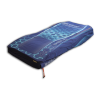
Step-by-step instructions for replacing the top cover of the Isolibrium support surface.
Detailed procedure for replacing the bottom cover of the Isolibrium support surface.
Instructions on how to replace the pod assembly, including disconnection and removal steps.
Steps for replacing solenoid valves within the Isolibrium system, including tool requirements.
Procedure for safely replacing the power supply unit of the Isolibrium support surface.
Instructions for removing and replacing the main circuit board in the Isolibrium system.
Detailed steps for replacing the pump assembly in the Isolibrium system.
Instructions for replacing the fan responsible for the Low Air Loss function.
Procedure for replacing the cooling fans located in the foot box of the Isolibrium.
Steps for replacing the sensor board, including disconnecting hoses and cables.
| Brand | Stryker |
|---|---|
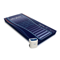
| Model | Isolibrium 2971 |
| Category | Medical Equipment |
| Language | English |