EENN
www.stryker.com 2971-109-0 01 REV B 1-57
Service
Sensor board replacement
Tools required:
• Zipper pull tool or equivalent
• Needle nose pliers
• ESD system
Procedure:
1. See Foot box cover access on page 1-40.
2. Properly ground yourself (see Protecting against Electrostatic Discharge (ESD) on page 1-33).
3. Disconnect all six of the pod sensor hoses from the foot box by gently pushing inward on the coupling and pulling
outward on each of the hoses.
Notes
• When handling the pod sensor hoses, do not bend or kink the hoses.
• Pay attention to the sensor hose position and insertion color and number labels.
• During re-install, make sure to insert the hose and once you hit a stop, continue pushing until you reach a hard
stop.
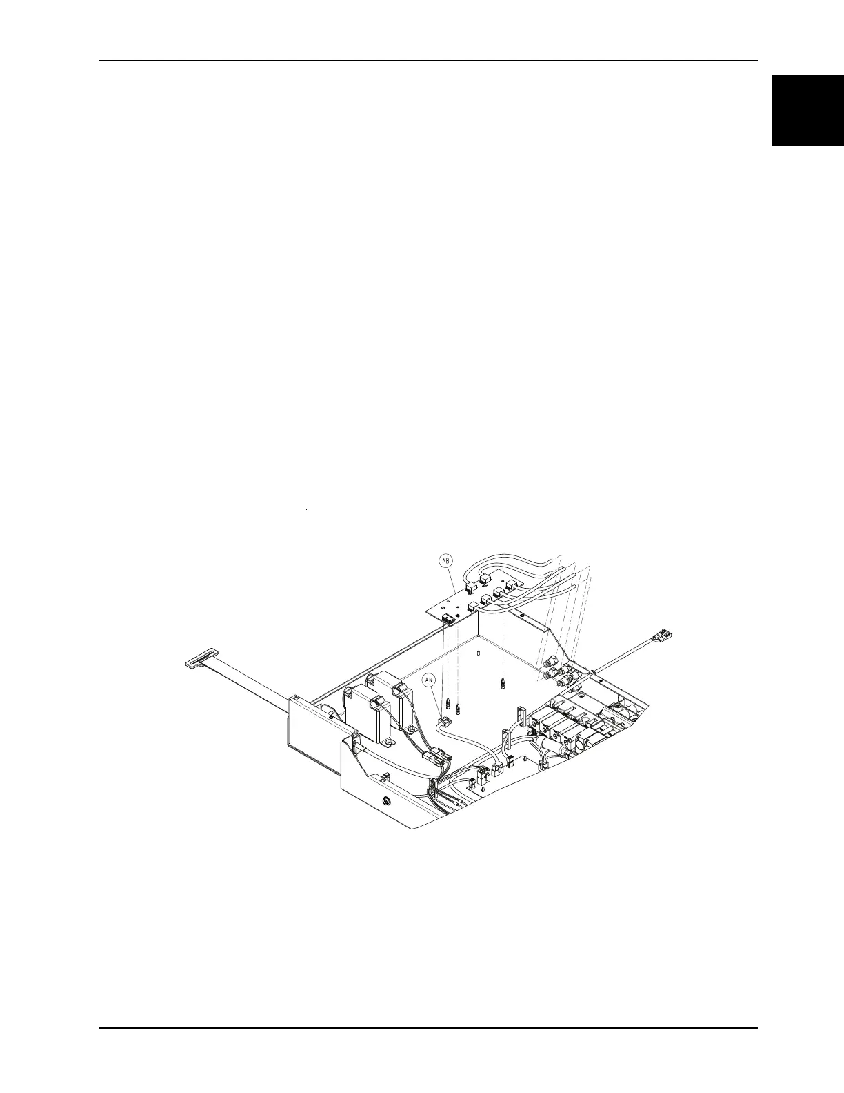
4. Disconnect the cable (AN) from the sensor board (AB) (Figure 1-30 on page 1-57).
5. Using needle nose pliers, lifting up slightly, disconnect the sensor board (AB) from the three plastic standoffs (Figure
1-30 on page 1-57).
Note: During reinstall, align the standoffs to the main board and press near the standoffs to seat the main board. Do
not bend the board.
Figure 1-30: Sensor board
6. Remove and discard the sensor board.
7. Reverse steps to reinstall.
Notes
• During reinstall, make sure to align the Velcro® patches.
• After installation, remove the zipper pull tool or equivalent from the zipper.
• Make sure that the watershed covers the zipper.