EENN
www.stryker.com 2971-109-0 01 REV B 1-51
Service
Pump assembly replacement
Tools required:
• Zipper pull tool or equivalent
• Diagonal pliers
• T15 Torx driver
Procedure:
1. See Foot box cover access on page 1-40.
2. Disconnect the pump power connector from the main board (connector F).
3. Disconnect the cable from the three wire retainers.
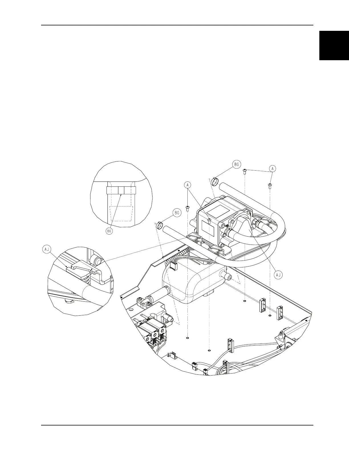
4. Using diagonal pliers, carefully cut the cable ties where the inlet hose connects to the manifold (BG) and the exhaust
hose connects to the resonator (Figure 1-24 on page 1-51). Do not cut the manifold barb.
Note: During installation, before cutting the end off of the cable tie, use the diagonal pliers to pry the slack out of the
cable tie (one to two clicks).
Figure 1-24: Pump assembly
5. Using a T15 Torx driver, remove the four screws (A) that secure the pump assembly (AJ) to the foot box (Figure 1-
24 on page 1-51). Save the screws.