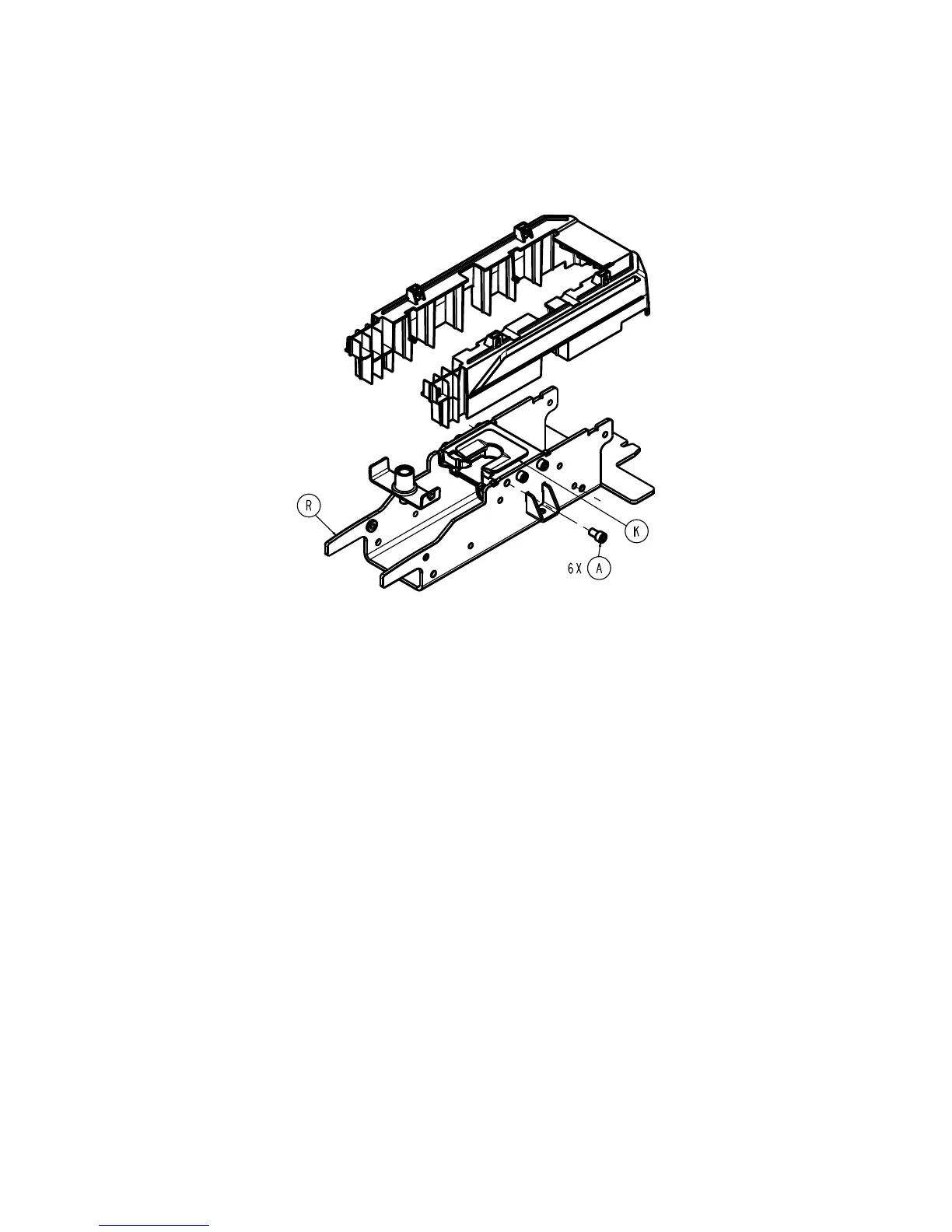
2. Using a ¼'' hex wrench, remove and save the six screws (A) that secure the foot end interface assembly (K) to the foot
end weldment (R) (Figure 3).
NNoottee -- Torque item (A) to 300 in-lb.
3. Remove the foot end interface from the lower release link by sliding it toward the head end.
4. Reverse steps to reinstall.
5. Verify proper operation before returning the product to service.
Torque item A
to 300 ± 15 in-lb
FFiigguurree 33 –– RReeppllaacciinngg tthhee ffoooott eenndd iinntteerrffaaccee aasssseemmbbllyy
IInndduuccttiivvee pprriimmaarryy bbooaarrdd rreeppllaacceemmeenntt ((ooppttiioonnaall))
TToooollss RReeqquuiirreedd::
• T27 Torx driver
PPrroocceedduurree::
1. Unsnap the floor plate cover to gain access to the electrical connection.
2. Disconnect the red and black wires from the cable harness.
3. Using a T27 Torx driver, remove and save the six screws that secure the foot end top cover to the foot end bottom
cover.
4. Using a T27 Torx driver, remove the two screws (A) that secure the inductive charging assembly (C) to the foot end
weldment (Figure 4).
5. Remove the inductive charging assembly.
6. Remove the inductive primary board from the charging enclosure. Discard the inductive primary board.
NNoottee -- Do not dispose of as unsorted municipal waste. Refer to your local distributor for return or collection systems
available in your country.
7. Reverse steps to reinstall.
8. Verify proper operation before returning the product to service.
6392-009-002 Rev E.4 15 EN