- 24 –
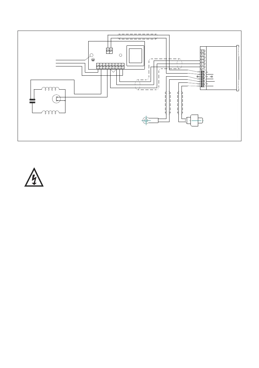
7.18 Wiring diagram:
7.19 Fuse: All models should be protected by a 3 Amp fuse.
7.20 Supply cord replacement:
The internal wiring within the terminal box is routed and secured
to ensure compliance with the electrical standard EN 60335–1.
It is essential that prior to any disturbance of this internal wiring,
all cable routing and securing details are carefully noted to ensure
re-assembly to the same factory pattern is always maintained.
7.21 If the supply cord is to be changed or damaged, it must be replaced by a
special cord available from Stuart Turner or one of its approved repairers.
MAIN WINDING
THERMOTRIP
CAPACITOR
START WINDING
B
L
U
E
B
L
A
C
K
L
E
N
230 VAC/1PH/50Hz
SUPPLY
GREEN/YELLOW
BROWN
BLUE
1
2
3
4
5
6
CONTROLLER
BLUE (LINK WIRE)
BROWN
BROWN
TEMPERATURE
SENSOR
PRESSURE
SENSOR
BLUE
BROWN
BROWN
BLUE
BLACK
BLUE
BLACK
BROWN
BROWN
BLUE
BROWN
BLUE
BLUE
BROWN
BLUE
BROWN
N N1 N2
L5
L4 L3 L2 L1 L
12 VAC
7
8
9
10
12 -VE
13 +VE
BLUE
BLUE (LINK WIRE)
NOT USED
NOT USED
11
Fig. 27