13
7.0 Input PCB removal
7.1 Perform procedure 1.
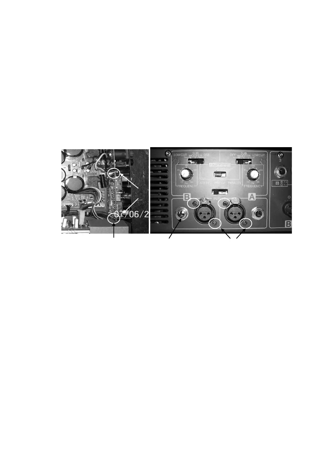
7.2 Remove M3X6 Pan Head Black Machine screws (2 nos.) fitted from inside.
7.3 Remove XLR to chassis screws M3X8 Pan Head Self Tap screws (qty 4 nos.), jack nuts (2 nos.) on rear.
7.4 Push the board backward and lift it carefully.
7.5 Disconnect the wire harnesses which are connected to Input board.
8.0 Input PCB Replacement
8.1 Re-connect harness as mentioned in 7.5
8.2 Place the Input board and align it to mounting holes on rear & re-fit the hardware as mentioned in 7.3 & 7.2.
Internal screws Jack Nut XLR Screws
9.0 Front Control PCB removal
9.1 Perform procedure 1.
9.2 Remove the control knobs on front.
9.3 Remove the transformer by removing bottom bolt.
9.4 Disconnect the wire harness going to control pcb.
9.5 Remove mounting screws M3X6 Pan Head Machine screws (qty 4 nos.)
9.6 Push the board backward & then lift it upward carefully.
10.0 Front Control PCB Replacement
10.1 Place the Control board and align it to mounting holes & re-fit the hardware as mentioned in 9.5
10.2 Re-connect harness as mentioned in 9.5
10.3 Re-fit the transformer as mentioned in 9.3
10.4 Re-fit the knobs as mentioned in 9.2
M3X6