14
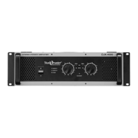
Control board Control/Led board
DJA2500 DJA4000
11.0 LED PCB (DJA2500) removal
11.1 Perform procedure 1.
11.4 Disconnect the wire harness going to Led pcb.
11.5 Remove mounting screws M3X6 Pan Head Machine screws (qty 2 nos.)
11.6 Push the board backward & then lift it upward carefully.
12.0 LED PCB (DJA2500) Replacement
12.1 Place the Led board and align it to mounting holes & re-fit the hardware as mentioned in 11.5
10.2 Re-connect harness as mentioned in 11.4
Led Pcb Mounting screws
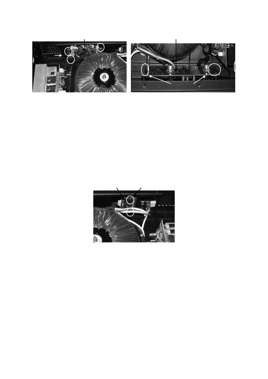
12.0 Output Board removal
12.1 Perform procedure 1.
12.2 Remove wires going to output board
12.3 De-solder binding post connector from inside.
12.4 Remove Speak-on connector screws (M3 X 6 Machine screws) & Jack nut (DJ2500) on rear
12.5 Push the board inside & lift it upward carefully.
13.0 Output board Replacement
13.1 Place the Output board to its position.
13.2 Re-fit hardware as mentioned in 12.4.
13.4 Re-solder the binding post leads and connect the wires as mentioned in 12.2
Mtg.
screws
Transformer
Mtg.screws