27
AIR BOOSTER 2
© STULZ SpA . – all rights reserved EN/10.2018/IT30I
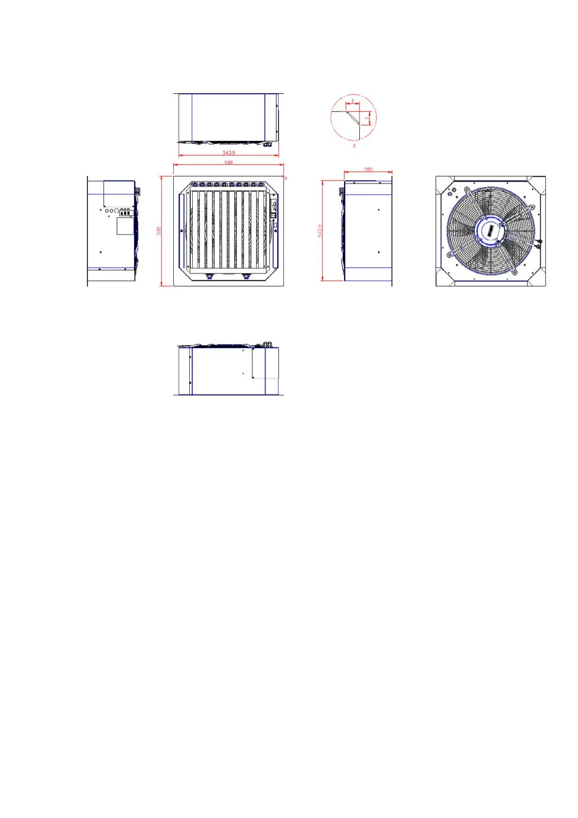
6.3. Drawings
7. Installation
Unpack the unit taking care to not damage its exposed parts. Before discarding the packaging,
make sure no parts or documents have been left inside. Check that the supply voltage is as
designated.
The installation and handling of the units may be hazardous as they form a system with electric
components. Only skilled personnel may repair, inspect or maintain the units. The installation of
an Air Booster 2 is similar as fixing an air diffusion grill on the false floor. It's necessary a minimum
space of 150 mm under the unit to guarantee the correct operation of the fan. Please follow the
indications below.
1. Select the location of the unit on the false floor, in a position that can allow a suitable flow of cold air
to all servers;
2. Remove the floor tile where Air Booster 2 unit will be positioned;
3. Insert the unit in the false floor using the internal handles of the unit;


 To Next Page