5 © STULZ GmbH – all rights reserved EN/03.2016
steam humidifier iNstruCtiONs
Setting the rotary switch S1
Power supply Steam capacity [kg/h]
2 4 8 10 15
200V 1N~ 0 0 - - -
208V 1N~ 1 1 - - -
220V 1N~ 2 2 - - -
230V 1N~ 3 3 - - -
200V 3~ - 4 8 C -
208V 3~ - 5 9 D -
220V 3~ - 6 A E -
230V 3~ - 7 B F -
380V 3~ - 0 4 - 8
400V 3~ - 1 5 - 9
415V 3~ - 2 6 - A
460V 3~ - 3 7 - B
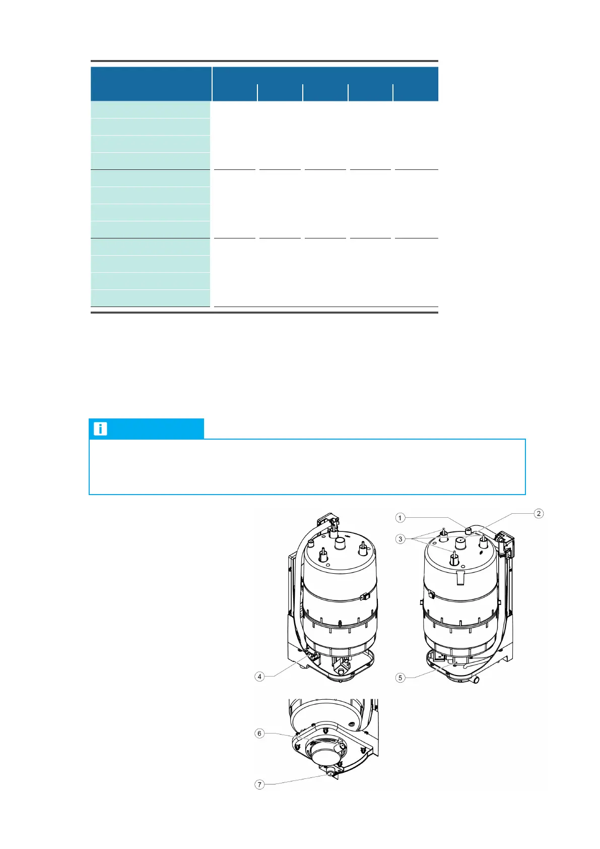
11.1.2 Supply connections
Legend:
1 Level sensor
2 Steam outlet connector ø22.5 - 30 mm
3 Heating electrodes
4 Inlet valve
5 Outlet valve
6 Drain connector ø30 mm
7 Water supply connector G 3/4“
NOTICE
We recommend the installation of an Aqua-stop valve in the water supply of the humidifier. In
addition to this, the room, in which the A/C unit with the humidifier is installed, should be equip-
ped with a water detection system.
The steam humidifier is installed and electrically connected in the A/C unit. The local regulations of the water
supply company are to be complied with when making the hydraulic connection.