LO
HI
E/0310/50/28
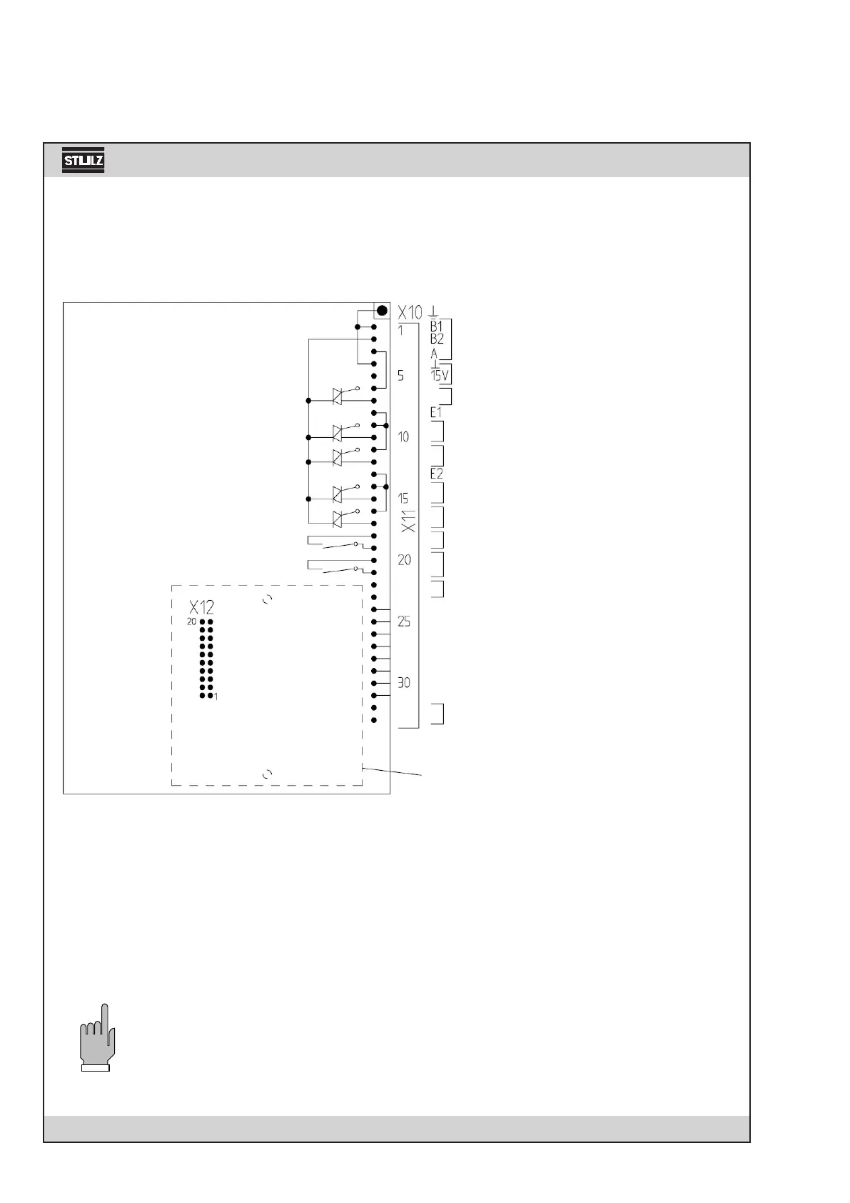
7.2 Connection Diagram of Processor Board C1002
24 V~
Sensor
Fan
shut valve / compressor 1
open valve / dehumidification
Reheat 1
Reheat 2 / Sequencing out
Humidifier
Alarm / Sequencing out
Sensor input 0-20mA
Airflow 1. module
Filter
Reheat
Humidification 20µS/cm
Ultrasonic 5 µS/cm* / high pressure comp. 1
Remote On/Off / Sequencing in
Aux1- Water detector / Sequencing in
Aux2- Fire detection* / low press. comp. 1
Monitoring RS 485
Extension card
X10: flat-cable plug 6.3 • 0.8
X11: connection terminal 33 pins
X12: extension plug 20 pins
* If an extension card is installed, the inputs for Ultrasonic 5µS/cm and Aux2/fire are situated
on the extension card.
The sequencing uses the standard inputs for Remote on/off and Aux1/water detector and the standard
outputs for reheat 2 and the common alarm.
If the input for Aux1/water detector and/or the output for reheat 2 are required, an extension card must be
installed, which provides an input/output for the sequencing.
This way the water detector input and the output for the 2nd reheat are provided on the processor board
again.
T
H