EasyManua.ls Logo

Stulz CyberOne EC DX User Manual

Stulz CyberOne EC DX
51 pages
To Next Page IconTo Next Page
Page #1 background imageLoading...
Page #1 background image
CyberOneEC
Installation, Operation and Maintenance Manual
C
hilled Water Systems
12 35 kW Systems
Vertical Floor Mounted, 60 Hz Data
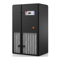
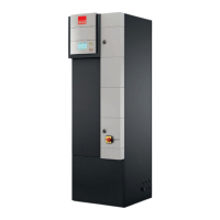
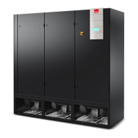
CyberOne EC DX
Installation, Operation and Maintenance Manual
Perimeter Precision Air Conditioners
7-35 kW / 60 Hz

Table of Contents

Questions and Answers:

Stulz CyberOne EC DX Specifications

General IconGeneral
BrandStulz
ModelCyberOne EC DX
CategoryAir Conditioner
LanguageEnglish

Summary

1.0 Introduction

1.1 General System Overview

Details the CyberOne EC system, its manufacturer, and manual importance.

1.2 Product Description

Describes system types, capacities, configurations, and features.

1.3 Safety Guidelines

Explains safety symbols, notes, cautions, and warnings.

1.3 Safety Guidelines

1.3.2 Safety Summary

Provides crucial safety warnings for installation, operation, and maintenance.

1.4 General Design

1.4.1 Electrical Compartment

Details the location and safety features of the electrical compartment.

1.4 General Design

1.4.2 Circuit Breakers, Heaters, and Fans

Explains component protection, optional heaters, EC fans, and sensors.

1.5 Optional Equipment

Lists and briefly describes optional components like humidifiers and detectors.

1.6 Free-cooling Operation

1.7 AWS Operation

2.0 Installation

2.1 Equipment Receiving and Inspection

Guides on inspecting the unit upon delivery and handling shipping damage.

2.2 Moving and Storing Equipment

Instructions for safely moving and storing the unit before installation.

2.3 Site Preparation

Details requirements for the installation site, including clearances and access.

2.3 Site Preparation

2.2.1 Conditioned Space Requirements

Specifies environmental conditions for the installation space.

2.3 Mounting and Placement

Guides on unit placement, leveling, and securing.

2.3 Mounting and Placement

2.3.1 Precision A/C Unit Mounting

Details mounting procedures for the main unit and optional floor stands.

2.3.2 Outdoor Equipment Installation

Provides guidelines for installing remote condenser units.

2.4 Air Distribution Connection

Explains how to connect ductwork for air supply and return.

2.4.1 Downflow Air Patterns

Describes typical air patterns for downflow configurations.

2.4 Air Distribution Connection

2.4.2 Upflow Air Patterns

Describes air patterns for upflow configurations with plenum boxes or ducting.

2.5 Optional Field Installed Equipment

2.5.1 Floor Stand and Remote Display Installation

Details installation of optional floor stands and remote displays.

2.5.3 Remote Sensor Installation

Guides on mounting the remote temperature/humidity sensor.

2.6 Piping Connections

2.6.1 Refrigerant Piping

Details field-installed refrigerant piping for split systems.

2.6 Piping Connections

2.6.1 Refrigerant Piping Specifics

Specifics on traps, insulation, line sizing, and materials for refrigerant piping.

2.6.2 Water/Glycol & Condensate Systems

Covers water/glycol piping, condensate drain, and optional pump installation.

2.6.4 Humidifier Water Supply

Instructions for connecting the water supply to the humidifier.

2.7 Utility Connections

2.7.1 Main Power Connection

Explains main power supply requirements, nameplate data, and wiring.

2.7 Utility Connections

2.7.1 Main Power Connection Details

Covers voltage tolerances and buck/boost transformer applications for single-phase units.

2.7 Utility Connections

2.7.1 Main Power & Control Wiring

Details three-phase unit wiring, control system wiring, and optional equipment wiring.

2.7.4 Air-Cooled Split Systems Wiring

Covers field wiring for split systems, remote condensers, and condensing units.

2.7.4 Air-Cooled Split Systems Wiring

2.7.4.1 Remote Condenser Control Wiring

Explains control wiring requirements for remote condenser models.

2.7.4 Air-Cooled Split Systems Wiring

2.7.4.2 Remote Condensing Unit Wiring

Details control wiring for remote condensing units.

2.7.5 Glycol System Wiring

Outlines wiring for glycol-cooled systems and pump packages.

2.8 System Charging Procedures

2.8.1 Water/Glycol Systems Charging

Notes that these systems are factory charged and require no field charging.

2.8 System Charging Procedures

2.8.2 DX Unit Charging Requirements

Provides best practices for performing DX unit refrigerant charging.

2.8.3 Remote Air-Cooled Systems Charging

Covers removing nitrogen charge and performing charging on remote air-cooled units.

2.8 System Charging Procedures

2.8.4 R407C Refrigerant Characteristics

Details the properties and safety considerations of R407C refrigerant.

2.8.5 Estimating Refrigerant Charge

Explains how to estimate refrigerant charge using tables and examples.

2.8 System Charging Procedures

2.8.6 Preparing System for Charging

Outlines steps for leak detection, evacuation, and system preparation before charging.

2.8 System Charging Procedures

2.8.7 Refrigerant Charging Procedures

Details initial charging and fine-tuning of the refrigerant charge.

2.8 System Charging Procedures

2.8.7 Refrigerant Charging Procedures (Continued)

Specific procedures for fan cycling, variable speed, and flooded head pressure control charging.

2.8.8 Refrigerant Characteristics Tables

Provides pressure/temperature settings and saturated pressure tables for R407C.

2.9 System Settings and Adjustments

2.9.1 Pressure Limit Switches

Explains the function and fixed settings of high/low pressure limit switches.

2.9.2 Air-Cooled Head Pressure Controls

Details various head pressure control methods for air-cooled systems.

2.9 System Settings and Adjustments

2.9.2 Air-Cooled Head Pressure Controls (Continued)

Describes intelligent control, flooded head pressure control for air-cooled units.

2.9.3 Water/Glycol Head Pressure Controls

Explains how head pressure is maintained in water/glycol cooled systems.

2.9 System Settings and Adjustments

2.9.3 Water/Glycol Head Pressure Controls (Continued)

Details adjustment procedures for water/glycol system pressure controls.

2.9.4 Humidifier and EC Fan Adjustments

Covers adjustments for humidifier capacity and EC fan speed control.

2.9.6 TEV and Hot Gas Reheat

Explains Thermal Expansion Valve function and optional Hot Gas Reheat operation.

2.9 System Settings and Adjustments

2.9.7 Hot Gas Bypass Options

Describes snap acting and full floating hot gas bypass systems.

3.0 Commissioning, Operation & Decommissioning

3.1 Commissioning and Start-Up

Details the process of commissioning and starting up the unit.

3.0 Commissioning, Operation & Decommissioning

3.1 Commissioning and Start-Up (Continued)

Describes testing cooling, heating, humidification, and dehumidification functions.

3.1.2 Controller Programming

Information on microprocessor controller programming and settings.

3.2 Unit Decommissioning

Procedures for safely decommissioning the unit and recovering refrigerant.

4.0 Maintenance

4.1 Periodic General Maintenance

Outlines general maintenance tasks and the importance of a checklist.

4.1.1 CyberOne EC DX A/C Unit Maintenance

Specific maintenance tasks for the A/C unit, including filters, fans, and coils.

4.1 Periodic General Maintenance

4.1.1 CyberOne EC DX A/C Unit Maintenance (Continued)

Covers maintenance for condensate pump, condenser, and humidifier cylinder replacement.

4.2 Troubleshooting Overview

Troubleshooting: Pressure and Blower Issues

Addresses low suction pressure, valve failures, coil icing, and blower failures.

4.2 Troubleshooting Overview

Troubleshooting: Controls and Condenser Pressure

Covers erratic controls, high/low condenser pressure, and blower failures.

4.2 Troubleshooting Overview

Troubleshooting: Compressor and System Capacity

Addresses noisy compressors, starting failures, short capacity, and short cycling.

4.2 Troubleshooting Overview

Troubleshooting: Heater and Humidifier Inoperability

Diagnoses and resolves issues with the heater and humidifier components.

4.3 Field Service Procedures

4.3.1 Leak Detection and Repair

Details methods for detecting and repairing refrigerant leaks.

4.3.3 Refrigerant Piping Service

Covers replacement of refrigerant components and piping.

4.3 Field Service Procedures

4.3.4 Component Replacement and Cleanup

Covers compressor failure diagnosis, standard/acidic cleanup, and humidifier cylinder replacement.

4.3 Field Service Procedures

4.3.4 Component Replacement and Cleanup (Continued)

Details air filter replacement procedures and humidifier cylinder replacement steps.

Glossary

5.0 Product Support

5.1 Technical Support

Details how to contact STULZ for technical assistance and required information.

5.2 Obtaining Warranty Parts

Outlines the process for requesting and obtaining warranty replacement parts.

Installation Checklist

Maintenance Checklist

Glossary

Related product manuals